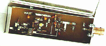
PHOTO 1: Top view of completed unit
This unit is an attempt to make the simplest possible signal source for 13cm without the usual grief of not finishing up on the right frequency. It has, of course, been constructed with Phase 3D in mind. It is built on a 4.25 x 1.4 x 1/16 inch epoxy glass fibre board.
Inspection of the circuit diagram shows that there are just three transistors: an FET oscillator, a BJT frequency multiplier (times 5), and an output transistor frequency quintupler. The oscillator starts with a readily available 96MHz crystal and multiplying this by 25 goes up to 2400MHz. The use of filters takes the guesswork out of finding the correct frequencies.
Figure 1: Circuit diagram
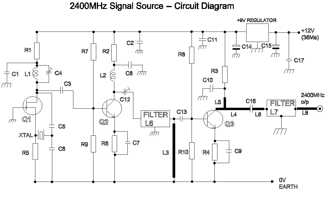
The output is -10dBm (100 microwatts) and the nearest sprog is on 1920MHz. This is -38dBm down. The output is too large for front ends (use an attenuator) but not sufficient for checking antenna systems (use a MMIC).
The FET oscillator uses a J310 in a standard circuit. No attempt has been made to obtain a signal clear of sprogs as the two filters will give all the cleanliness required. The oscillator gives 1 milliwatt drive to the 2N5179 quintupler. The output from the 2N5179 is fed into a Toko filter (Toko filters are the unsung workhorses of the VHF/UHF bands - what we do without them!). Some attempt has been made to match the 480MHz output to the filter and C12 is used to peak up the signal. The output from the Toko filter is approximately 1mW and is very clean.
Some care is now required over the final matching. The output from the Toko filter at 50 ohm is L matched to a transistor type AT41486 ( not too expensive) whose input impedance has been taken as 12-j8. The final in and out stages use microstrip lines. I use Chartpack rub down lines on the PCB before etching - but that's another story.
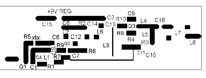
Figure 2: 2400MHz Signal Source pcb layout
Etched side of board showing tracks and placement of components. The board is 4.5" long, 1.5" wide and 1/16" thick and is double sided epoxy fibre glass. It is etched on one side only, the other side forming the ground plane. Careful use of a file will be needed to fit in the box.
The fifth harmonic from the AT41486 is matched into a Neosid filter. An earlier version used a variable capacitor but that did not work very well, so a microstrip line with the appropriately placed matching stub is used. The output impedance has been taken as 80-j48. For further details on this see UHF/Microwave Experimenters Manual chapter 6.
The output from the Neosid filter is again 50 ohm microstrip and the BNC socket matches up against the edge of the PCB, the metal extension on the back of the socket having been removed in the lathe. You may have to tune the Neosid filter to peak up the signal but adjustment of the Toko filter is not necessary.
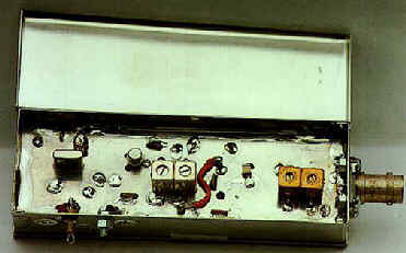
PHOTO 2: Underside view showing component layout:
Use the photo above to determine the position of various components with respect to the pcb layout diagram. "Earth" connections are made through to the groundplane side of the pcb, most of the components being fixed on the track side (see photo).
I have five spare etched roller tinned but undrilled double sided epoxy fibre glass boards for the asking. First come, first served - just send a SAE.
I am QTHR and the telephone number is
01608 644371 (before 10pm please).
You can email me at: john.brown@g3dvv.demon.co.uk
(MANY THANKS JOHN FOR THIS USEFUL ARTICLE....ALL WE NEED NOW IS FOR PHASE 3D TO LIFT OFF!......ed.)
R1, R2, R3, R4 100 ohm
R5, R6 220 ohm
R7, R8 3.8K
R9, R10 1K
Q1 J310
*Q2 2N5179 (Mainline)
Q3 AT-41486 (Mainline)
L1 125nH 5 turns spaced 22SWG 1/4" former
L2 28nH 2 turns 20SWG 0.13" long 13/64" ID 0 .15" leads
L3 0.62" long 0.02" wide Microstrip.
L4 50 ohm microstrip 0.105" wide with stub 0.274" from collector.
L5 50 ohm matching stub 0.363" long and 0.105" wide
*L6 Filter 480MHz Toko type 252MX-1552A (Cirkit)
*L7 Helical filter Neosid type 00510241 (LMW)
L8 50 ohm microstrip 0.105" wide
C1,C2 0.01uF
C3 4.7pF
*C4 12pF trim
C5 10pF
C6 33pF
C7,C8,C9 1nF trapezoidal (Piper)
C11 1nF
C12 10pF Sky black (Piper)
C13 22pF
C14,C15 4.7uF Tant
C16 100pF ATC (LMW)
C17 1nF feed-thru for power supply, placed on side of box.
*Xtal 96MHz (Bonex)
Tinplate box 7754 (Piper)
PCB.
Double sided. Epoxy fibre glass. 4.5"*1.4"*1/16".
Make sure board is 1/16" thick as industry standards vary
VR 9v reg 78L09 (Farnell).
The unit consumes approx 38mA