DB6NT will provide a different milled box to the one shown here (see G0IVA's photos)
All transceive switch is operated by the ptt switch on the driver transceiver. A built-in 4 watt attentuator permits the use of drivers such as the FT290, IC202, etc.
A control output for further stages is also included.
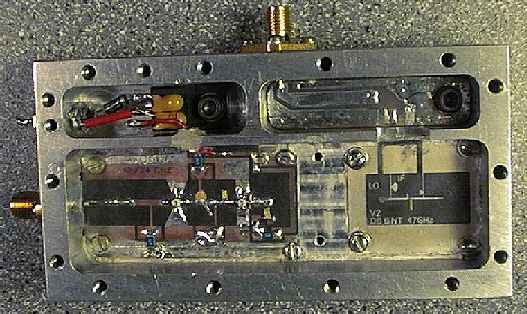
In the photograph above can be seen the following sections of the transverter which are common to the standard DB6NT design:
Lower Left: 12/24GHz doubler: In this section (assuming a 144MHz IF) 40mW of 11376MHz local oscillator input drive is doubled to 20mW at 23.472GHz. This is then fed, via a waveguide, highpass filter (Lower right centre) into a harmonic mixer, shown at lower right. The 23.472GHz LO output is fed via a probe into the waveguide filter and extracted by a second probe for the subharmonic mixer. The IF input line to the mixer can be clearly seen on the circuit board. This would be normally be 144MHz. G7MRF's driver and LO frequencies differ to these as he uses a 1296MHz IF.
Martin has produced his own milled box here so that two extra compartments are available:
Upper Left: Regulator psu for doubler,
Upper Right: 1296MHz IF input matching circuitry.
The sma socket in the wall of the milled box receives the 23cm drive.
![]() RETURN TO 47GHz DB6NT PHOTO GALLERY
RETURN TO 47GHz DB6NT PHOTO GALLERY