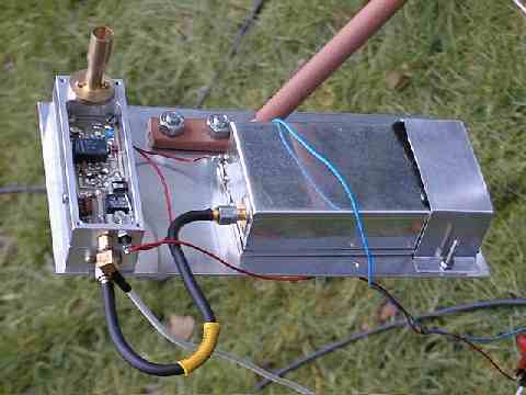
The open milled box shows the power supply, IF and control circuitry, while the doubler and sub-harmonic mixer are on a separate pcb in the other milled box beneath. The tinplate box is a 11-12GHz oscillator module.
The oscillator module has a clean output as a result of helix filters and microstrip resonators being used in the design.
DB6NT specifies some 30 to 40mW at 11.736GHz is needed to produce around 20mW at 23.472GHz. This in turn is used to sub-harmonic mix with the IF input of 144MHz to produce approximately 150 to 200 microwatts (uW) at 47.088GHz). The minute mixer diodes employed in the 47GHz transverter are Hewlett Packard type HSCH3251. MGF1302 GaAsFETs are used in the 11.7/23.4GHz doubler.
The 47GHz waveguide/horn, clearly shown above, is fed by a short probe from the output line of the subharmonic mixer. David, G0IVA, designed this horn to match a 35cm offset fed dish (ex satellite TV).
![]() RETURN TO 47GHz DB6NT PHOTO GALLERY
RETURN TO 47GHz DB6NT PHOTO GALLERY