Have you ever wondered just how accurate your frequency counter really is? It's tempting to accept it as being "spot on", especially if you are working at HF or even VHF. For microwaves, however, you need more than average accuracy. The odd Hertz or two inaccuracy at say 10MHz is multiplied up a thousand or more times by the time you get to 10GHz. That's 2kHz out at 10GHz for 2 Hz inaccuracy at 10MHz.
The little unit pictured here showed my Racal-Dina frequency counter to be 0.2Hz high at 10MHz .... that's around 207Hz high at 10.368GHz... ie less than a quarter of a kHz... not bad! It's certainly a lot better than using crystal standards multiplied up to the microwave bands from a low frequency.
I have used mine to set up a very stable and accurate 100MHz sythesiser, the Adret 5104, so that, when that is set to 108MHz and driving a simple diode multiplier, I can get highly accurate marker signals on all microwave bands to 24GHz and very reasonable accuracy on 47GHz.
This "poor man's caesium clock" has now replaced my MSF locked source as the primary station standard as it does not suffer from the vagaries of propagation that affect the 60kHz MSF signal, particularly in the evenings. That doesn't mean I have thrown the MSF source into the bin! Far from it, it it still a very useful standard and will always be there as a fall-back unit.
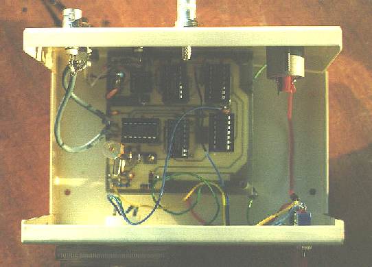
The G4NJU (Dave McQue) unit is described in the RSGB's January 1999 issue of RadCom. Full construction details and schematic are given in that article. I was able to use a PCB, kindly made up for me and a few friends by a fellow amateur, but it would be possible to assemble the unit on perforated board (ie "veroboard") or even in "dead bug" style on a piece of single-side pcboard. My version is assembled into a small metal cabinet some 10 x 15 x 7cm.
The idea behind this accurate frequency standard is to lock a stable 10MHz xtal oscillator to the highly stable TV line frequency used in the UK by the BBC1, BBC2 and Channel 4 transmissions. Similar stability can be obtained from the ZDF television transmissions broadcast from the Astra satellite. Other TV broadcasts may not have the same kind of long term stability, especially if they are frequently switched from one network to another. The ones mentioned above seem to be locked to a rubidium standard.
In this unit, composite video is fed into an integrated circuit sync separator (an LM1881) and then into one half of a 74HC74 monostable to provide an output of 15,625Hz. This frequency is then divided by 2 in the other half of that chip to give a 7812.5Hz output which is then fed into a 74HC86 XOR gate used as a phase detector. A 10MHz crystal oscillator is made from one section of a 74HCU04 hex inverter. The free-running crystal oscillator is accurately zeroed to 10MHz by means of a trimmer capacitor. A BB515 varactor diode is used for the electronic tuning voltage provided by the phase detector. To get the necessary comparison between the crystal oscillator and the 7812.5Hz signal produced from the TV sync, the 10MHz crystal output is divided down by 1280, through two chips, a 74HC390 and a 74HC393, to also give 7812.5Hz. The two signals are then fed into the phase detector. When in phase quadrature, the detector will produce a voltage half way between the DC supply voltage and ground. Deviations in frequency will result in a change in this voltage, plus or minus the centre figure. This voltage is used to vary the capacitance across the crystal oscillator via the BB515 varactor diode. This keeps it spot on the frequency determined by the very accurate TV sync.
A 100uA "centre zero" meter is employed to indicate phase lock....
it stays in the centre when lock is obtained. All that is needed in adjustment
is to first make sure the 10MHz crystal oscillator is as near accurate
as possible and then apply video (in my case taken from a rear mounted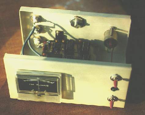 BNC socket on a video record set to one of the local BBC channels). You
will then notice the meter drift around either side of zero and very quickly
settle down in the mid-position, indicating lock.... that's all there is
to it!
BNC socket on a video record set to one of the local BBC channels). You
will then notice the meter drift around either side of zero and very quickly
settle down in the mid-position, indicating lock.... that's all there is
to it!
A group of four amateurs, including myself, found a minor problem with the circuit. The 74HCU04 10MHz oscillator would sometimes not oscillate when switched on from cold. Touching pin 1 would get it going. A 1 megohm resistor was tried from this pin to ground and it appeared to work for a short time but the problem came up again. Replacement of the chip with a 74HC04, a buffered version of the one in the original article, cured the problem, but at the expense of a slightly poorer phase noise performance. This is of no consequence if the frequency standard is to be used soley to check counters and the like. However it would not be good enough for a unit employed as part of a microwave phase locked system where the signal was to be multiplied up in frequency many hundreds of times. Subsequent communication with the designer of the unit led to the discovery that the 2K2 resistor in series with the crystal could be gradually lowered in value until the crystal oscillator started up every time. However, you should try to keep this resistance as high as possible consistent with good oscillator startup.
The output of the unit is 100kHz, 1MHz and 10MHz, all at 5 volts. It is therefore recommended that 0.01uF "blocking" capacitors are soldered in series with each output. The outputs can then be fed into receivers, counters and other equipment in complete safety.
Try this little unit yourself... you won't be disappointed. Be sure to find out about the stability of your local TV signal though!
![]() RETURN TO SIMPLE TEST GEAR INTRODUCTION
RETURN TO SIMPLE TEST GEAR INTRODUCTION