|
Two examples of the Flyswatter Antenna are described here.The first one is by Doug, GW3ATM and the second is by Mike, G0JMI. Click here for Mike's information. Many thanks to both GW3ATM and G0JMI for their interesting information |
 |
 |
In an effort to develop a decent 10GHz home station antenna system, Doug, GW3ATM, has turned to the Flyswatter Array. Pioneered many years ago in the UK by Mike Walters, G3JVL and Dain Evans, G3RPE, it does not appear to have received the attention it deserves. When correctly set up, the system offers a very good performance, often comparable to a moderately sized dish antenna at the same height. Many of us have problems erecting a dish at a reasonable height because the most efficient way of feeding it usually involves having the microwave transverter either immediately behind or just below the dish and effectively out of reach for easy access. The associated weatherproofing problems deter many folk from using this approach. Feeding the antenna via a long length of waveguide is another alternative but this usually means having some sort of rotary waveguide joint at the base of the waveguide and using a length of flexible waveguide or coax section to get around the rotator. Losses are necessarily greater when this latter method is employed.
The flyswatter antenna uses a very low loss feeder … air! Basically,
the microwave transverter is placed at or near ground level, where it
can easily be adjusted and even taken indoors during periods of non-activity.
Some distance directly above the transverter is a plane reflector, angled
so that the radiation from the transverter’s antenna (which is conveniently
a small dish or even a horn) is reflected out horizontally to the surrounding
area (see diagram right). The lower antenna doesn’t need to be exactly
underneath the plane reflector as the angles involved can easily be adjusted
to compensate for any deviation from the vertical.
Small offset fed dishes provide excellent feed antennas for flyswatter
systems since the transverter and its feedhorn can be mounted so that
they do not point up into the sky from where they might get an input of
rain during bad weather. They also tend to be more efficient than rear
fed dishes using, for example, the “Penny” feed.
The distance between the dish and the plane reflector is effectively a
compromise based upon the relative gains of both dish and reflector (which
in turn are a function of their physical dimensions). Unfortunately there
is not room here to discuss this aspect in the detail it deserves! Paul
Wade, W1GHZ, presented a fascinating paper on the subject at Microwave
Update , held in Philadelphia, USA in September 2000. The paper can be
found in the Proceedings of Microwave Update 2000 (available from the
ARRL) and on Paul’s outstanding website at: www.w1ghz.org
. Interested readers should refer to either of these resources.
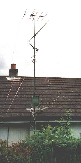
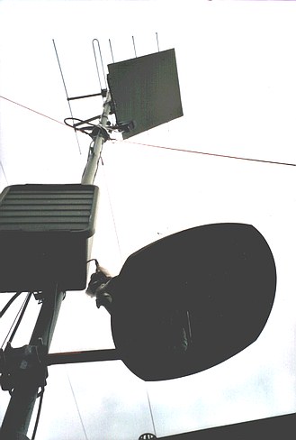
GW3ATM’s flyswatter system consists of a 48cm diameter, ex-BSB, offset
fed dish, mounted just above gutter level on a rotary, guyed pole, next
to his bungalow. The dish is fed with an ex-Amstrad, sat-TV feedhorn (widely
available at rallies). The aluminium, plain reflector is 1mm thick and
measures 23 inches by 33 inches. It is fixed 11 feet above the BSB dish.
A sat-TV screw jack, fixed on a bracket on the opposite side of the mast
to the reflector, is used to vary the tilt angle of the flyswatter. The
pole, dish, plain reflector and transverter are so arranged that they
all rotate together. If the dish and reflector did not move together there
would be a change in the polarisation of the reflected signal. This problem
was clearly demonstrated in Paul Wade’s Microwave Update 2000 talk,
when he used a laser pointer and plain reflector to “beam” the
light at the four walls of the lecture room!
GW3ATM places his 5 watt 10GHz transverter in a weatherproof box, mounted
on the same pole and just below the dish, so that a short and easy connection
can be made to the offset feedhorn.
Results so far have all been in receive mode only but have been very encouraging.
From his home at Llandogo, Monmouthshire, he can hear the Cleeve Common
10GHz beacon, GB3CCX, at good strength from two directions, via reflections
from nearby commercial towers. He cannot hear this directly at ground
level. G4UVZ has also been heard and he believes he can just detect the
new Dorset beacon, GB3SCX. Doug is looking forward to the coming microwave
“season” when he hopes to work many stations several hundred
kilometres away. Rainscatter propagation should also provide very interesting
results now that the reflector’s tilt angle can be remotely adjusted.
The Flyswatter antenna system offers the home station operator a convenient
and efficient way of making the most of his or her location.
Mike, G0JMI, has also designed a home station Flyswatter Antenna system. Just click on the arrow here to take a look ...