|
CALLSIGN: GB3KEU LOCATION: IO93GH38, MEADOWHEAD, SHEFFIELD, UK (Now IO93NN, Finningley near Doncaster) HEIGHT ABOVE SEA LEVEL: 190m FREQUENCY: 5760.925MHz KEYING MODE AND MESSAGE: FSK ~ 400Hz shift. GB3KEU IO93EH38 (twice) and 25 seconds of key down carrier. The message was changed to IO93NN in 2013 when GB3KEU was moved to Finningley) ANTENNA: Slotted Waveguide 10dB gain and omni directional POWER OUT (ERP): 25 watts
|
|
|
The PA is clamped to the large heatsink bolted onto the outside of the enclosure. The enclosure has a rectangular hole cut out of it to enable the PA to make direct contact with the heatsink. This hole is made very waterproof using some exterior grade sealant. The DC power connections to the PA are made with a connector at this point so that the module can be removed if necessary, without disturbing the rest of the beacon. Below the PA is the DB6NT driver module. This feeds the PA via a 3dB attenuator which provides a 50 ohm load for the driver in case of PA failure and also reduces the drive power down to a level where just 2.5 watts reaches the antenna from the PA.
The driver and OCXO are mounted on an aluminium plate which also serves as a small heatsink. The DB6NT beacon needs this as it runs quite warm under normal conditions. To the right of the driver you can see the DC input feed and block connector. A short DC lead with Power Pole connectors is wired in parallel with the main feed so that a small Sealed lead Acid battery can be connected here to allow the whole beacon to be moved with just the local oscillator running. If the power were completely removed from the beacon, the oven in the oscillator box would have to warm up again and the oscillator would drift for a while until it became stable. I have found in the past that OCXOs do not always come back the same frequency if they are switched off for long periods! The G8ACE OCXO is shown in the lower left corner of the box. The two ten turn trimpots adjust the actual beacon frequency (upper trimpot) and the FSK deviation (Lower trimpot). Just above the OCXO is the switch bank which has three switches controlling DC to the various modules. Their status is shown by LEDs at each switch. An LED is also soldered onto the PIC keyer to indicate the keying sequence. The keyer is a small PCB mounted on standoffs (actually large value resistors!) soldered to the lid of the OCXO. The whole beacon assembly is mounted inside a large plastic waterproof box, rated to better than IP66. Even then, I took the precaution of drilling a small diameter hole through the side of the box facing downwards just in case any water manages to creep into the box. Hopefully the beacon will give many years of useful service! |
|
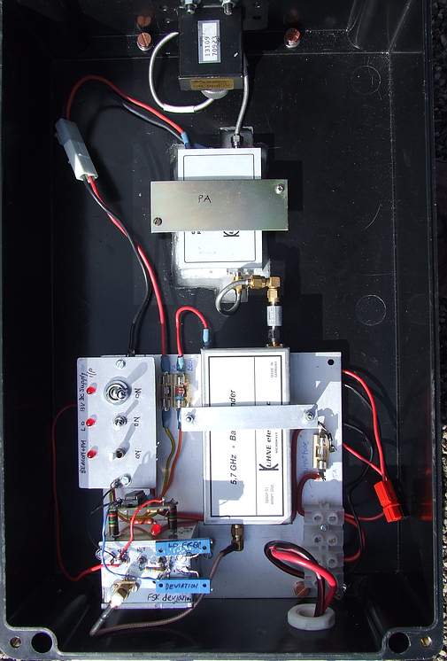 This
photo shows the inside of the enclosure. At the top is the coax
to waveguide transition with the DB6NT below it. The transition
and waveguide flange of the slotted antenna are inside the box so
that they can be bolted tightly against the upper wall of the
enclosure, trapping a generous amount of exterior grade sealant
between them! Outside the box, the waveguide antenna is protected
by a plastic rectangular section, cable trunking sleeve which has
a weatherproof end cap at the top.
This
photo shows the inside of the enclosure. At the top is the coax
to waveguide transition with the DB6NT below it. The transition
and waveguide flange of the slotted antenna are inside the box so
that they can be bolted tightly against the upper wall of the
enclosure, trapping a generous amount of exterior grade sealant
between them! Outside the box, the waveguide antenna is protected
by a plastic rectangular section, cable trunking sleeve which has
a weatherproof end cap at the top.