 A
DUAL MODE HORN FOR 10GHz USING STANDARD COPPER PIPE FITTINGS
A
DUAL MODE HORN FOR 10GHz USING STANDARD COPPER PIPE FITTINGS
Updated October 2000
Now with improved performance! (see below)
There are many dish feed designs to be found in the various microwave texts and journals. When the writer changed from a "Penny Feed" 18 inch dish system to a perforated Amstrad, 60cm satellite dish (with offset feed) a couple of years ago, he found a tremendous improvement on 10GHz narrowband. A circular, dual mode, feed horn, taken from a Marconi "Blue Cap" (Amstrad) LNB was available and pressed into service as a dish feed and used with a "brute force" transition to WG16 (i.e a WG16 rectangular flange butted against the circular port on the horn!! As G8AGN showed (1), this horn is not of optimum dimensions for the amateur band and has a rather poor return loss. His article described a much more efficient scaled version of the Amstrad feedhorn. To make Barry's feedhorn requires machining facilities and the writer, not having such luxuries, stuck with the original Amstrad horn until early 1995. There was room for improvement however and the following paragraphs describe the route taken to improve the dish feed efficiency and thus recover some precious dBs of antenna gain.
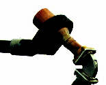
The first of the two diagrams below shows the W2IMU dual mode feedhorn recently made to feed a 60cm ex-satellite dish for 10GHz portable operation. Dual mode horns are very suitable for dishes with f/Ds of around 0.5 to 0.6. They can produce a very symmetrical radiation pattern in both E and H planes, unlike many other feeds. Not only that, it is common for other feeds to have different phase centres in each of the planes, thus making it difficult to properly focus the dish. Most of us manage to muddle through with our penny or dipole/reflector feeds and get results but we are most likely operating with dish efficiencies well below 45%. The dual mode horn is also a very "clean" feed in that side and rear radiation is reduced to a low level ( better than -30dB). This is due to the dual mode nature of the feed. The small section of the horn supports the lower waveguide mode and flares into the wider horn section which supports two waveguide modes. The size of the flare determines the relative amplitude of each mode and the length of the larger section is designed to cancel the two modes at the outer edge of the horn. This cancellation greater reduces sidelobe radiation and thus enables more energy to be propagated towards the dish reflecting surface (2).
Being more sharply defined, the horn sees the dish and not the ground behind it and thus is also a quieter feed in that less ground noise is picked through "spill over" around the edge of the dish. Because the phase centres of both planes are almost identical the horn is easier to position at the correct focal point of the dish.
The writer recommends the excellent article (2) by N1BWT which appeared in Microwave Update '94. Here, Paul Wade, N1BWT, makes an exhaustive study of several types of dish feed and highlights the critical importance of the following factors when trying to get the utmost in dish efficiency:
The offset, circular horn dish feed seems ideal in view of the above criteria. A properly designed dual mode horn would enable high orders of efficiency (at least over 60%) to be obtained.
The horn is based on two articles that appeared in Microwave Update '91, published by ARRL (3). The original W2IMU design used a flared pipe reducer that had a 40 degree flare angle (due to a short taper length). This was in excess of the more appropriate 30 degrees taper required for 10GHz. As a result, a ring of 3mm diameter soft copper pipe had to be fitted inside the reducer at the wider end of the taper. This seemed an unnecessary complication to the author of the second article in Microwave Update '91 which showed a modification made by WA5VJB, of 10GHz EME fame. Here a reducer of longer taper length was used. Thus the flare angle was reduced to a more suitable figure for the 10GHz band allowing a more gradual transition from one horn to the other
A visit to the local D.I.Y superstores found plenty of 22mm i.d. copper pipe and couplers for the same but no suitable reducer fittings or 42mm straight couplers. Only a specialist plumbers' supplier could come up with the necessary items! The writer's supplier is shown at the end of this article (5). It is important to obtain solderless fittings. Any solder inside the feed will cause unacceptable losses. The diagram is largely self-explanatory but you may note the sliding adjustment provided at the junction of the horn and the 22mm o.d. copper feedpipe. (Note also that couplers are measured internally, while normal tubing is measured externally).
| NEW INFORMATION NOW AVAILABLE:
A meeting with Paul Wade, W1GHZ, at Microwave Update 2000, revealed that he had been working on computer simulations of this horn and applying several lengths to the wider, outer section of the feedhorn. Paul is convinced that a shorter total length of the wider section works better than the 64mm shown in the above diagram. In fact a figure of 47mm produces an almost perfect radiation pattern in both E and H planes and an opitimal horn for dishes of 0.6 f/D. So, to shorten the horn, merely saw or machine off a length of the straight 42mm coupler so that the total length of the end section (from the end of the flare to the mouth of the horn, is 47mm. Make sure the cut is accurately done so that the open end of the horn is perfectly even. In case you are wondering how the writer arrived at 64mm for the original PHO horn, well the figure was taken from the original design by W2IMU ... and we still don't know how Dick arrived at that figure!
Many thanks to Paul Wade, W1GHZ, for his interest in this antenna
feed and for providing the simulation results.
|
Using a directional coupler, a good VSWR can then be obtained. An insertion of some 11mm or so is needed here. The narrow end of the reducer can be slotted and fitted with a hose clamp to enable a secure fit once the VSWR is set. The copper pipe feed could be extended all the way down to the transverter provided the pipe is as straight as possible. 22mm pipe is both cheap and efficient as a 10GHz feeder but bends should be avoided as far as possible or mode changes may occur. The writer uses a 100mm length of pipe whose far end has been shaped, with a suitable forming tool, to fit a WG16 flange (4). A short length of flexiguide then connects the whole feed system to the portable transverter.
No definitive measurements have been made on the writer's system but, for interest's sake, the horn was tried on the Astra satellite channels and excellent pictures were received, at least as good as the normal Amstrad type horn, even though the new horn was designed for a frequency almost 1 GHz lower.
The finished horn was mounted on the Amstrad feed clamp, although the plastic clamp had to be filed a little to make it slightly wider than the fitting for the old Blue Cap horn.
Adjustments were made using the local GB3MLE beacon on 10368.925MHz. A more appropriate method might be to use a low power source located several hundred feet from the dish and mounted at the same height. Field adjustments can easily be made as all the parts are "slideable" and can be permanently fixed with solder on the exterior of the horn when satisfied.
2. Secrets of Parabolic dish antennas - by Paul Wade, N1BWT.. ARRL MICROWAVE UPDATE '94
3. A simple dual mode (IMU) feed antenna for 10386MHz - ARRL MICROWAVE UPDATE '91 and RSGB MICROWAVE NEWSLETTER, September 1990.
10GHz IMU feedhorn update - by WA5VJB. ARRL MICROWAVE UPDATE '91
4. Forming tool for circular pipe to WG16 transitions - RSGB MICROWAVE MANUAL Vol.3, page 18.6
(Telephone 0114 2501 122). Prices (as in 1996) are shown below (add 17.5% VAT & postage). The prices may have risen since the writer last checked.