|
A
VERSATILE TRANSVERTER INTERFACE FOR THE FT817 - page 2
|
|
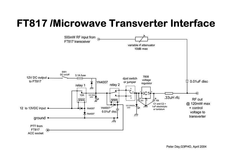
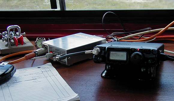
The FT817 power lead is connected to the fused 12V output socket on the interface, while the FT817’s BNC VHF antenna front panel connector is connected via a short length of coax to the socket marked ‘500mW RF input’. The FT817 power output is reduced to 0.5W by means of the transceiver’s menu. A coax cable of any convenient length then connects the interface to the microwave transverter. My own system uses a 15 foot length of 50 ohm double screened coax here, the variable attenuator in the interface being adjusted to give 120mW at the far end of this cable. To obtain full send/receive control of the transverter by the FT817 PTT line, an 8 pin mini DIN plug is wired up to take a short, thin coaxial lead from the transceiver’s ACC socket (pin 2) to the PTT phono socket on the interface. When the microphone PTT button is pressed or the morse key activated, pin 2(‘TX ground’) of the ACC socket of the FT817 is grounded to pin 3 and in turn completes the ground connection of the coil of Relay 2 in the interface. This applies 12 to the 7808 regulator IC. Depending on the configuration of the DPST slider switch in the interface, a +8VDC control voltage will be applied to the IF output line on either RX or TX. |
 |
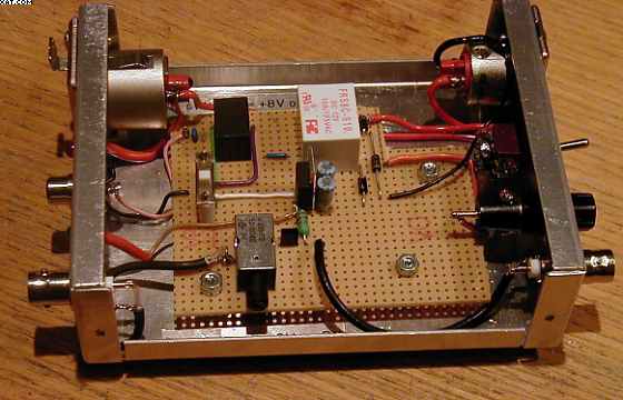 |
Construction: There’s nothing special about this module. One off units like this don’t need a purpose made PCB unless you like your gear to look fancy! The enclosure is a small aluminium box I had in the “come handy drawer”and I used some perforated board that has strips of copper foil on one side (called “Veroboard” in the UK) for the circuitry. The board should be populated with the various components and tested before it is put into the small aluminium enclosure, as shown in the photographs. The box is drilled at both front and rear aprons to take the various connectors and switches, making sure that all I/O leads to the FT817 go to one apron and the outputs to the microwave transceiver to the other. |
|
COMPONENTS:
I decided not
to switch out the attenuator when receiving as my transverters have
more than adequate gain in reserve to overcome the 6dB or so of
attenuation in the IF line. This is probably the case for most systems. Relay 1:
This is for polarity reversal protection. Any 12V DC type
will do here so long as the contacts can handle a few amps. I used
one rated at 10A. To reduce overall load on portable batteries choose
one with low coil current. Relay 2: This is the main control relay. I used a miniature 12VDC type with 1 amp contacts. With both relays,
don’t forget to put 1N4001, or similar diodes, across the coils
to prevent “back EMF” effects. RF choke:
A small axial lead 0.33uH type 8 Pin mini-DIN
connector (male: This is needed for connecting the interface
to the ACC socket on the rear of the FT817. Make sure that the inner
of the thin coax lead goes to pin 2 and the shield to pin 3 of the
male connector. Use the pin numbers on the connector itself to absolutely
sure you have the correct pins. Wrap some insulation over nearby
pins, one of which, pin 1, carries +13.8V from the FT817. Short
this to ground at your peril! Refer to the FT817 manual diagram.
On the ACC socket pin 2 is named “TX ground” and pin 3
“ground”. Do not us e the PTT pin on the DATA socket. Control Voltage
Sense Switch: A small slider switched was mounted on three pins
that are soldered through the perforated board. Pin 1 of the 7808
regulator is connected to the slider. In the schematic, pins A and
C are connected by the switch to simulate IC202 control switching
while pins C and B provide FT290 type switching. Internal IF
coax lead: Summary: References: DOWNLOAD COMPLETE CONSTRUCTIONAL ARTICLE HERE: FT817 interface v 2.pdf
|