As with the 47GHz system, a 1296MHz IF is used, simplifying image filter requirements at the millimetric frequencies.
|
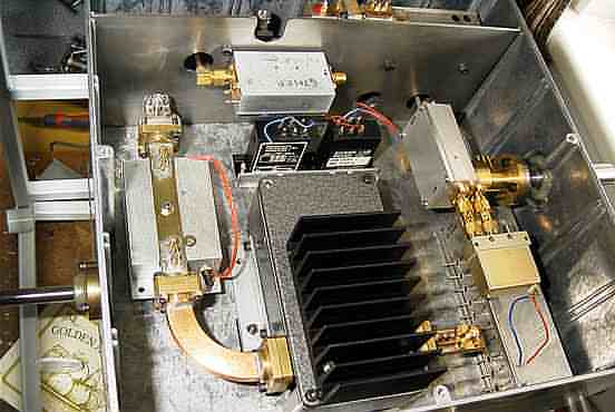
The 24GHz
box is shown here. Remember that it is bolted to the 47GHz transverter
so that a quick flip can change bands from one to the other.Much more use
of waveguide is seen here, in contrast to the 47GHz system. The availability
of some Teletra 23GHz systems a few years ago provided useful coax to WG20
transitions and a nice 24GHz/12V coaxial relay. Note the liberal use of
matching screws in the waveguide sections, to ensure good matches at each
flange ... every fraction of a dB helps at 24GHz!
As with the 47GHz system, a 1296MHz IF is used, simplifying image filter requirements at the millimetric frequencies. |
| The circular waveguide output transition to the dual mode horn feed is home constructed and can be seen in more detail in this second photograph. Again, matching screws ensure a good match. The assembly shown above projects through the wall of the transverter box and through a hole in the rear of the Procom dish. A dual mode horn is thin slid over the section on the right of this photograph. | 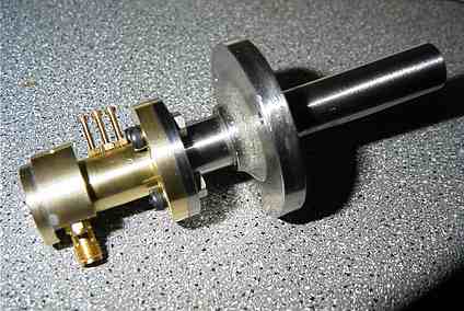 |
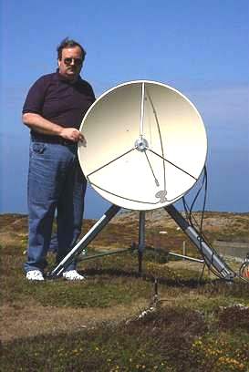 |
Finally, here is a photo of Martin, G7MRF, with his portable millimetre station for the new millenium ... readers will certainly congratulate him on a fine effort and for the photographs and information which will be a source of inspiration for others. |