|
The New Radio Shack at G3PHO 2002 |
| Since December 1980, when I returned
the the UK after five years in New Zealand, I have lived in a an old Victorian,
stone-built house just a mile and half from the centre of Sheffield. Though
in a poor location for amateur radio, it was an ideal size for bringing
up my family of mum, dad and the four kids! The house was built in 1861
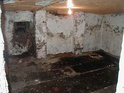
and, as was the fashion in those days, was provided with two large cellars
underneath the building. For many years, I have used one of them as a workshop,
housing the usual metal and woodworking tools that the average "Mr D.I.Y"
tends to accumulate but the other cellar,until April 2002, was left in
its original, dirty state and, for most of the time, full of junk!
Up to April 2002, all my amateur radio operating and construction had been in a succession of spare bedrooms and, as our children gradually left home, expanded until TWO rooms had been overwhelmed by the hobby! |
 |
|
My next
door neighbour also had cellars like mine and needed a study for his work
in the medical field. He had one of his cellars converted into a really
useful room, removed from the general household activities and a place
that could be left has he liked! I liked the idea so much that in
2002 I decided to do the same to my house. This result is what you see
in these photos. Apart from the antennas on the roof of the house, there
is now no evidence of amateur radio in the "normal" part of the house itself,
all my gear being located beneath the living room floor!
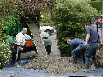
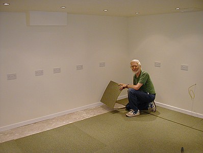
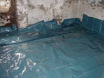
First of all, the original stone flagged floor had to be removed and the earth beneath dug out to accommodate a 4 inch (100mm) thick concrete floor. The concrete was laid over a thick plastic membrane sheet as shown in the photo to the left. Eventually this membrane was extended to line the original walls of the cellar as well, the aim being to make the new room free of any damp that might seep through from outside. It has certainly succeeded as there is absolutely no trace of damp some 8 months later. |
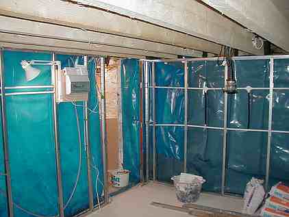
| Once the plastic wall lining had been fixed, a metal framework, designed to hold plasterboard walls, was constructed from floor to ceiling. Before the plasterboard was installed, I wired each of the four walls with separate mains circuits, each having ten (five double) sockets spaced out along each wall and at bench height. Each of the four circuits is protected by its own trip contained in the consumer unit shown in the photo on the right. |
|
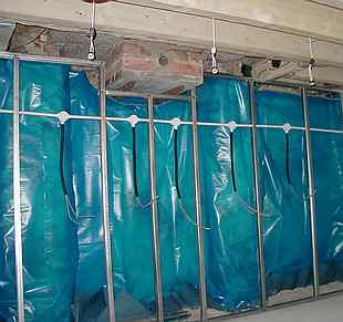 |
This photo shows some of the mains wiring, running inside plastic conduit threaded through holes in the metal framework. The wiring for each socket comes down from the main harness via flexible conduit. The whole thing makes a reliable and serviceable system. Hanging from the ceiling joists are the fittings for the recessed halogen ceiling lighting. Each wall is also on a separate lighting circuit. The idea behind all this is that each wall is independent of the others so that if a fault occurs on one wall's equipment it does not trip the whole room. This is especially important as one wall has frequency standards and measuring equipment that is permanently switched on, for ultimate stability. However there is a master switch, just outside the shack door that can switch off the whole room is case of an emergency! |
| After the walls had been plastered, I painted them in a pleasant shade of cream and covered the floor in carpet tiles. The row of double mains sockets can also be seen in the photo on the right. Coming out of the wall on the right is the station ground (earth) lead connected to copper rods driven deep into the ground immediately behind the wall. |
|
 |
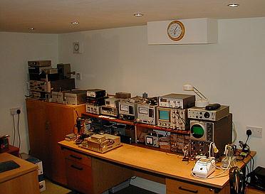
The photo
on the left shows (left to right) part of the test gear bench, 10GHz and
5.7GHz transverters on top of the filing cabinet, the station operating
desk (160 metres to 70cm) and, on the near right, the video editing and
computer bench.
The antenna feedlines and rotor cables (all 20 metres long) come into the shack via a plastic tube which extends from outside the house, just above ground level, and through the 30cm thick stone wall and into the space between the shack ceiling and the lounge floor above. The cables are then routed down the wall in the white trunking shown in the photo. |
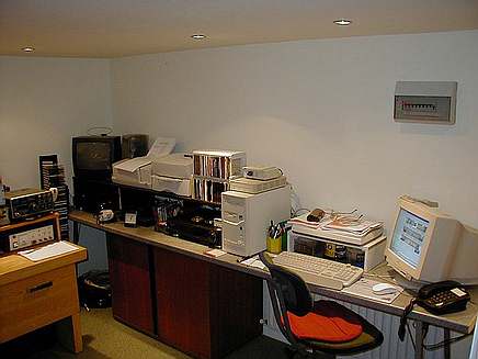
| This photo to the right shows the video editing and computing bench. Underneath the bench is a central heating radiator which keeps the whole room at a most pleasant temperature! Just outside the shack there is a useful storage area at the foot of the cellar steps, where I keep the portable microwave equipment, ready for use at a moment's notice! |
|
Other test gear, out of view in this photo, includes wavemeters covering 1GHz to 50GHz, a simple Noise Figure meter, directional couplers and various microwave mixers. The metered unit on the front of the bench is a 144MHz high gain noise amplifier, built to a design by G4NNS. It is used to measure Sun and moon noise by feeding in microwave transverters at a 144MHz IF. Full constructional details appeared in the RSGB Microwave Newsletter in January 2003. A PDF file of this article is available on request from the webmaster. The fourth wall of the room, not pictured here houses cupboards and shelf units in which books, spare parts and components are kept. |
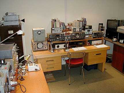
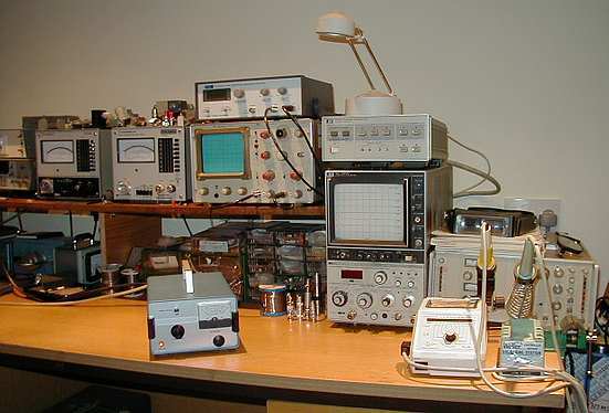
The bench
shown in these two photos to the left is perhaps the most important of
all the areas in my shack! It houses all my test gear and contains the
desk upon which I build most of my microwave equipment, leaving only the
metalwork (making enclosures, etc) to be done in the adjacent workshop.
On the far left of the upper photo here you can see my frequency standards. These are left running permanently and, indeed, have only been switched off once in four years ... when I moved my equipment down to this room. The standards include a highly accurate 10MHz/1MHz/100kHz source, given to me by Andy Talbot, G4JNT, who has spread three or four of these excellent units around the UK ... many thanks Andy! I use it to lock my Racal-Dana frequency counter and my two Adret 5104 90-120MHz synthesised sources. I can check all sources with a TV locked source. The lower left photo shows my two Marconi microwave power meters. With the heads I have I can read quite accurately to 24GHz. Higher than that is "intelligent guesswork!" The oscilloscope with the green screen is a general purpose one and is shown here connected to a Thandar Spectrum Analyser adapter which gives useful traces from almost DC to 1.1GHz. To the right of the scope is a Hewlett packard HP 182/8558B Spectrum analyser which covers the basic range of 100kHz to 1500MHz. I use a variety of surplus mixers with this to "look" at microwave frequencies above 1.5GHz and can easily see the area around 24GHz for example. To the right of the HP Spectrum Analyser, behind the two temperature controlled soldering stations, is a 0 to 1.6GHz sweeper. The unit on top of the HP analyser is an HP 8750A normaliser, quite useful for smoothing out the analyser trace and also for storing one trace for comparison with one in real time. |
Due to my very poor location I do not have home
station microwave equipment at the present time. However I hope to install
a mast head transverter for 23cm and maybe 10GHz one of these days. However,
while ever the body and mind still allow it, I shall continue to operate
the bands above 1.3GHz on a portable basis!
| RETURN TO FRONT PAGE MENU | CLICK HERE |