|
5.7GHz
IN TWO DAYS!
~by Peter, G3PHO |
 |
(This article
was updated and revised on 7 September 2001)
I dont know what it was that encouraged me to
email Michael Kuhne, DB6NT for one of his 5.7GHz transverter kits but Im
very glad I did! I normally do my construction work during the winter months
but, after improving my 24GHz system over the 1999 Christmas period with
one of Michaels amplifiers, I received his latest catalogue. Inside was
an ad for the 3rd Generation 5.7GHz Transverter. The Sterling/Deutche
Mark rate was at the very favourable rate of 3.3DM/£1 in early May,
2000, so I took the plunge and bought a 6cm kit, the MKU57G2. The kit cost
just £190 ( or 598DM). It arrived within a few days of ordering and
it literally took only two days to build into its tinplate box! A further
day was spent making a suitable enclosure for the complete transverter
(i.e. including c/o relay, metering and IC202 interface).
On opening the parcel from
Kuhne Electronic, I was immediately impressed by the high standard of presentation.
There were two plastic, compartmentalised cases containing the components.
Each compartment was labelled with the component value. The construction
manual is in English and the circuit, pcb layout and other diagrams, including
photographs are beautifully presented. Most of the components are
very small SMD types and are a very good test of ones eyesight! |
|
The transverter is of singleboard
construction on RO4003 substrate. The DB6NT catalogue guarantees an RF
output of more than 200mW. I found it easily did that and much more. A
receiver noise of 1dB is claimed for the module but by the time I had the
chance to check it on precision noise figure measurement equipment I had
assembled a complete transverter with change over relay and sma output
connector. the NF at the antenna connection measured a very creditable
1.25dB.
The pc board is of excellent quality, gold flashed
on the ground plane side and with plated-through ground connections from
the circuit side. It fits into a tinplate enclosure 33 x 55 x 150mm. SMA
connectors are used for IF input and the separate antenna connections to
RX and TX. Feedthroughs are used for the 12V DC input line, PTT, power
monitor and the +12V output for external relay control. Everything is provided
except for the external c/o relay at 5.7GHz.
As received from DB6NT, the transverter is configured
for a 144MHz IF but, with some slight component changes, it can be used
with a 432MHz IF. State which you want if you order the kit.
The actual construction presented no problems.
Before the active devices were installed, the pcb was checked for soldering
errors. The voltage regulators were then installed and checked for the
correct output. Then the bipolar devices were fitted and voltages checked.
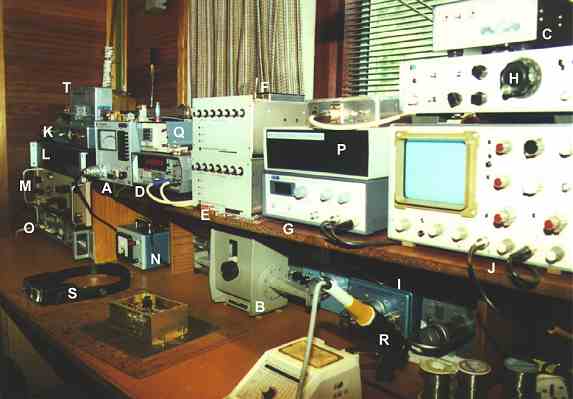
The module was set up on my test bench (seen here to the left) where the
LO was checked against my frequency counter and adjusted to 117MHz. Finally,
the GaAsFETs were installed and bias levels checked. After that the tune
up was very straight forward since Michael provides clear instructions
with relevant voltage levels for the various test points. The filters tuned
up beautifully. No one was more surprised than I was when the marker from
my Adret 5401 synthesizer/diode multiplier arrangement was heard very loud
and clear at T9, bang on 5760.100MHz! |
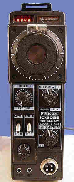
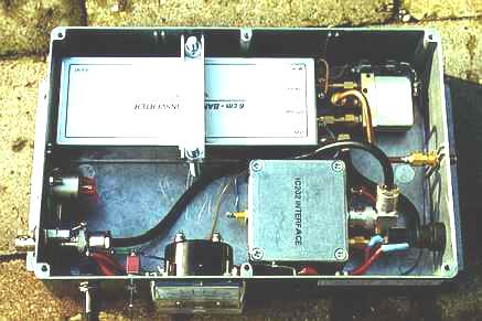
| I use the IC202s for my microwave IFs. Both have
been modified to give 120mW out instead of the more usual 3 watts. Since
the DB6NT kit comes with an IF input attentuator for a 3W input,
I had to modify this to allow the lower input value to drive the unit.
This meant reducing the 470 ohm resistor in the PI-attenuator to 100 ohms.
The fitted variable 100 ohm pot could then be adjusted for correct IF drive
to the mixer. The DB6NT transverter, as it stands, is configured
to use an FT290 prime mover where +9 volts or so is present on the coax
during transmit. This voltage switches a keying transistor into TX mode.
I decided to leave the DB6NT intact and to make a simple two transistor
keying interface for the IC202 so that, on pressing the microphone
switch, the interface would ground the DB6NT PTT terminal, thus switching
the module to TX. The IC202 has around +4.5 volts present on the coax inner
on RX mode rather than the TX mode of the FT290. The interface was built
into a small diecast box. |
|
|
|
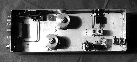
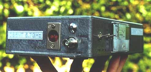
The tinplate box housing the transverter, the
IC202 interface module and the microwave coaxial change-over relay were
then installed into an Eddystone diecast box (220mm x 145mm x 55mm) which
had been pre-drilled and sprayed with silver hammer finish paint. Switches,
input and output connectors plus a meter to monitor both the 12 volt DC
input and the TX RF output where also fitted. The photographs on this page
show the details. The 12 volt change-over relay came from a Teletra 23GHz
TX/RX unit. It is an excellent relay and, of course, is to
some extent wasted at this lower frequency. However it is the only 12 volt
DC one I have, the others being 28 volt Transco types. To keep the DC requirements
simple I therefore treated the 5.7GHz transverter to a good relay! In any
case it fitted across the SMA connectors on the outside of the tin plate
box just perfectly! I used two male-male couplers here plus a short length
of semi rigid coax to reach the bulkhead mounted SMA output socket. |
I can easily get over 300mW output from this transverter.
At present I have a moderately low gain antenna system for it
. A 60cm
offset dish with pyramidal feedhorn designed for 0.7 f/D. As a result,
I am getting around 28dB or so gain from the antenna. Nevertheless,
I have been very pleased with the results so far, with 9 separate stations
worked in two portable sessions, the best being G0HNW/P at 265km.
I can thoroughly recommend the DB6NT
5.7GHz transverter to anyone contemplating getting going on this interesting
microwave band. You can buy one ready made (and 8 watt PAs also) but you
can save a lot of money and at the same time get an immense amount of pleasure
by building up a kit. Similar singleboard transverter kits are available
for the other microwave bands up to 10GHz.
Congratulations to all at Kuhne Electronic for
a fine piece of kit!
For further details and a catalogue, contact:
Kuhne Electronic, Birkenweg
15, D95119 NAILA/Holle, Germany
Telephone: 0049 9288
8232 Fax: 0049 9288 1768
E Mail: kuhne.db6nt@online.de
Website: http://www.db6nt.com
|
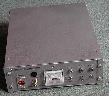 In
early 2001 I rehoused this transverter in a new, homemade enclosure and
included a surplus 1.25 watt solid state PA. The photograph on the left
shows the finished item. I have further plans to replace the PA with a
12 watt one and to add a G8ACE oven controlled crystal oscillator. This
should then give me the frequency stability and accuracy I presently enjoy
on 10 and 24GHz! In
early 2001 I rehoused this transverter in a new, homemade enclosure and
included a surplus 1.25 watt solid state PA. The photograph on the left
shows the finished item. I have further plans to replace the PA with a
12 watt one and to add a G8ACE oven controlled crystal oscillator. This
should then give me the frequency stability and accuracy I presently enjoy
on 10 and 24GHz!
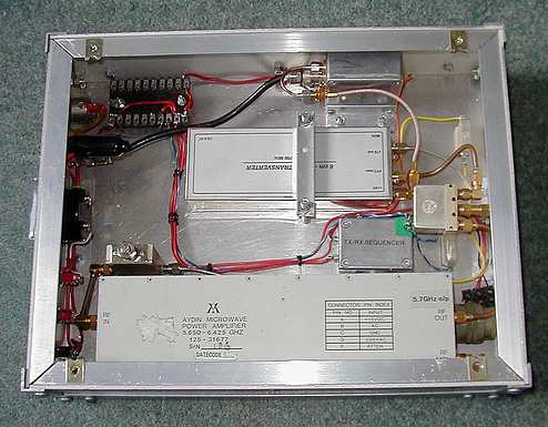
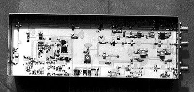
The photo above shows the new layout. Most of
the items in the enclosure are from the original 300mW transverter but
the large module at the bottom of the picture is the 1.25W PA. Fortunately
this operates with a single 12 to 13 volt input and thus nicely fits
in with the rest of the modules which are also +12V operated. A transmit/receive
sequenced changeover module, contained in the small diecast aluminium
seen here between the DB6NT transverter and the PA, was fitted as a
precaution against damaging the sensitive HEMT receiver RF stages. The
PA requires only a few hundred microwatts of drive at 5.7GHz so I fitted
a variable 38dB connectorised attenuator between the DB6NT module and
the PA input (see above the PA on its left hand side). This enabled
an optimum drive level to be set up.
In 2003 I changed the PA to a surplus 12 watt
amplifier that I had acquired at Microwave Update a couple of years
previously. With this kind of power output to the 1.2m dish I now find
I can quite regularly work the long 500km+ paths from my portable location
near Sheffield to French and Dutch stations on mainland Europe.
E.I.R.P.rules !!!!
|