
MODIFYING THE MICROWAVE ASSOCIATES"WHITE BOX"FOR 10GHz... updated January 2000 ... |
Read this first!
It is suggested you download this article and read "offline". If you are using Windows 98 you can save the whole page, including diagrams, by clicking "File - Save as -". Other browers will save only the text. You will need to save each diagram separately.
Alternatively, a "zip file" containing all the diagrams and the complete
text can be downloaded by clicking here:
MORE 10GHz WHITEBOX INFORMATION
This takes you away from "The World Above 1000MHz" so please come back when you've read the information!
INTRODUCTION
The following notes are based on work carried out on these MACOMM units by G3PYB, G3PHO, G8AGN and others. The notes do not pretend to be definitive or complete....they are merely a record of what was done in the early 1990s to get the units operational on the 3cm band. All stations concerned have had much success but have also had their share of problems, as you will read about herein!
There are two versions of the Microwave Associates "White Box" that have appeared on the UK surplus market (similar ones were also available in the USA)-- the RAPAC Central Sector transceiver and the RAPAC Subscriber Terminal unit. The former is a "base station" providing approximately 1 watt output on transmit and a receiver of some 5dB noise figure at 10.6GHz. The latter produces around 100-150mW on transmit (although some amateurs have 'encouraged' the units to give over 300mW) and a receive noise figure of around 11dB. The Subscriber terminal does not have a receive RF stage, unlike the Central Sector unit., hence the inferior noise figure. The following notes refer to the latter unit, the Subscriber Terminal Unit. Hundreds of these have become available over the last few years at a cost of around £100 in brand new condition. They represent outstanding value for money, the local oscillator unit or the transverter unit alone being worth more than that amount. They offer the amateur a relatively easy way of getting on the 10GHz band with an effective narrowband station. An additional outlay of £70-£80 or so (to cover the cost of a new crystal, portable psu components and a 10GHz coaxial relay) should be all that is need to convert the units to a complete 144MHz to 10GHz transverter
The modifications carried out by the author were aimed at making a PORTABLE
unit. If you wish to use the unit as a home station you can use the mains
psu that comes with the "White Box". Otherwise you will need to build up
a 12 volt DC input psu as described later.
GENERAL DESCRIPTION:
The Subscriber Unit comes in a heavy, waterproof, white case, complete with large heatsink on the back. Inside you will see a TWO milled aluminium boxes housing the TRANSVERTER UNIT and the PHASED-LOCKED LOCAL OSCILLATOR UNIT. These are easily identifiable as they are connected to each other via a short length of semi-rigid coax. The RF (Transverter) unit has waveguide output feeding a waveguide flange mounted on the outer case of the White Box. The other obvious unit is the "mains" power supply. It actually requires 55 volts AC input and can be retained if desired since it produces all the voltages necessary for a home station 10GHz transverter. The modules are mounted on a useful "tray".
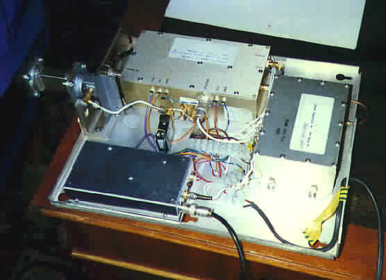
This photograph shows the two units as removed from the outer
case and remounted by the writer on the alumium tray, along with a portable
DC power supply and changeover (the lower left box). This photo shows the
system during its early modifications and testing. Note the addition of
a change over relay and sundry sma sockets. The local oscillator is the
right hand milled box, the other being the transverter module.
There are various other boards mounted on the inside of the White Box lid and on the aluminium tray containing the three units described above. These boards are superfluous from now on and should be removed and discarded (or put in the "junk box"). The first stage of the modifications is to remove the tray from the heavy box and then to remove the three main units from the tray, noting the various inter connections and preserving the original leads and connectors if the mains unit is to be employed eventually. The small pcb mounted on pillars at the top left-hand side of the tray can be discarded.
Figure 1 shows a generalised block diagram of the transverter or RF unit. It is wise to remove this unit from the tray (by carefully disconnecting the leads that come to it) and then, after taking off the upper and lower lids, marvel at the construction of this section of the "White Box"! It goes without saying that you should take the necessary precautions to avoid static damage to the various sensitive components within the unit. The RF output transistors alone were £135 each to replace when the author checked a few years ago, so be careful!
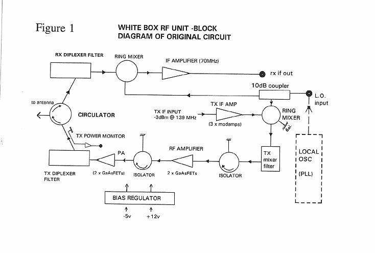
Study Figure 1 and relate it to the unit. Identify the various stages and become familiar with its physical layout. The Top Section of the RF unit contains two milled cavities, the larger of which contains a large p.c.board whose circuitry includes three modamps fed with the TX IF (around 139MHz in the original unit). This section will be slightly modified later. The smaller p.c.b. is a wideband RX IF amplifier. This will later be removed and replaced with a more efficient unit. Note the three coaxial sockets feeding the top section. These are clearly marked TX IF IN, RF IF OUT and TX MONITOR. The author replaced all three with BNC sockets but the original ones could be retained if you have connectors to match.
The lower section of the RF unit can be examined by removing the bottom lid. Figure 2 shows the layout of this section.
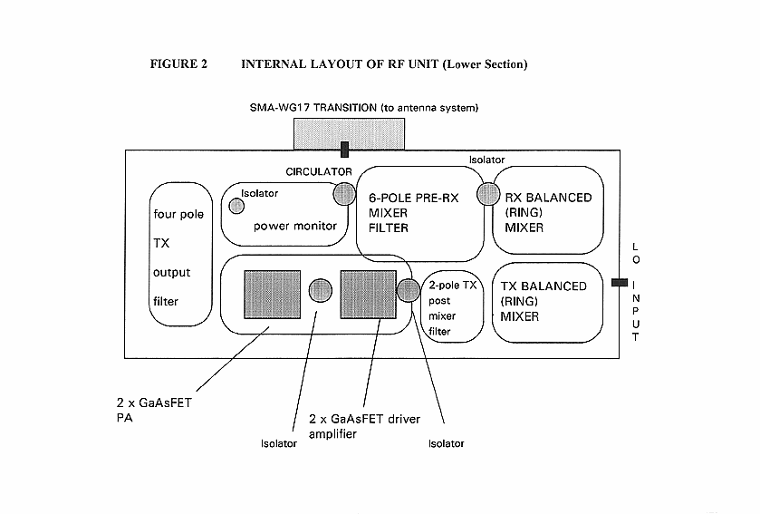
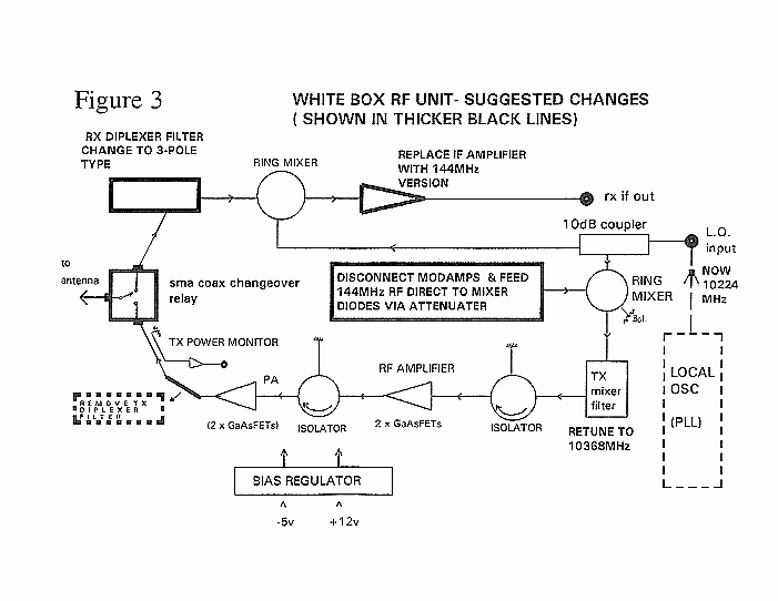
Some 40 to 50 mW of local oscillator (at 10GHz) drives two balanced mixers, on TX and one RX via a 10dB coupler. The RX mixer is fed with the 10GHz received signal via a circulator a six-pole filter and isolator. There is no preamplifier at 10GHz so the noise performance is not good enough (at 11dB) for serious amateur use (although the writer used his White Box without a preamp during a couple of contests and worked several stations over 250km with ease! Once a decent preamp was installed, though, a whole new world was uncovered!). The TX balanced mixer feeds a two-stage FET amplifier via a 2-pole filter and isolator, which in turn drives another two-stage FET power amplifier whose output, in turn, passes through a 4-pole filter and power monitor before reaching the SMA/waveguide transition via the output circulator. The lower section of the RF unit is to be modified to provide (a) separate SMA tx and rx sockets, (b) filters aligned in the amateur 10GHz band and, (c) more RF output at 10368MHz.
The changes to be made are outlined in Figure 3 and are separately detailed in later pages.
The LOCAL OSCILLATOR is housed in a separate, milled box and
consists of a crystal oscillator at a frequency just above 100MHz (the
author's was originally on 102.3539MHz), a VCO on approximately 1.7GHz
and a x6 multiplier. The frequency of the free-running VCO is controlled
by a DC ramp signal from a low frequency sweep circuit. In the unlocked
state, the multiplied X-band output sweeps across some 50MHz, centred
around 10.5GHz. The 1.7GHz signal is therefore phase locked to a
harmonic of the crystal oscillator and multiplied by a factor of six to
10GHz. Detailed circuitry for this unit can be seen in Figure
4 and Figure 5. The writer is indebted
to G4PMK and G3SEK for these circuits, traced out by them at the expense
of considerable patience! The local oscillator is a highly stable source
and once a brief warm-up time has elapsed, very accurate frequency resetting
on the 10GHz band is possible with the finished transverter.
The local oscillator's stability is enhanced by the use of a crystal
heater and an efficient AFC locking system. The modifications to
this unit include:
(a) changing the 100MHz crystal to one suitable to produce an
output at 10224MHz,
(b) further voltage stabilisation of the crystal oscillator transistor
to avoid "pulling" effects when changing from transmit to receive (noticeable
when using a portable 12 volt psu,
(c) the inclusion of l.e.d. indicators for TX, RX and LOCK states
and
(d) the inclusion of a "fine-tune" circuit to the AFC for accurate
frequency setting.
The original POWER SUPPLY requires 55 volts AC to produce the various DC voltages for the White Box. The writer has not used this supply since he built a portable one, running on 12 volts DC input. The original "mains" unit can, of course, be employed and this is possibly the easiest way of getting the gear working. Its circuit is shown in Figure 6. The various outputs are also shown.
A suitable 12V in/20V out portable supply was originally described in the May 1997 issue of the RSGB Microwave Newsletter. It employs an LM2577-ADJ step-up Voltage regulator chip. It was found essential to adequately screen the pcb and filter all leads entering and coming out of the box or strange effects became apparent on the local oscillator's signal!
The -5 volt supply is derived from a simple 7805 regulator which produces a positive voltage that is reversed in polarity by the very useful ICL7660 chip.
The supplies required by the "Whitebox" are:
+12 volts DC, switched between TX and RX
+20 volts DC at 500mA (very well regulated) for the Local
Oscillator and for the microwave coaxial antenna relay
-5 volts bias for the TX FETs
The circuits for both supplies are shown in Figures 7 and 8.
The portable supplies described produce up to 1 amp or so of 20 volts and 50 mA at -5 volts. Total current drain from a 12 volt battery is around 1 amp or so, depending on what extra circuitry is built into the equipment. The crystal oven or heater in the local oscillator is rather hungry for current but only for a short time after switch-on. Whatever supply is chosen it is essential to observe one simple rule....keep the -5 volt bias supply permanently connected to the RF unit. The GaAsFETs therein could be damaged if the supply is inadvertently left disconnected during testing. The other supplies are switched between transmit and receive, except of course the 20 volts to the local oscillator unit, which runs continuously.
Another portable supply can be found on page 220 of the ARRL's Microwave Update 1991. The '91 Update contains complete details of the American way of modifying the "White Box" and is well worth reading.
It is assumed that suitable DC supplies have been arranged before the
detailed modifications that follow are attempted.
It is essential to replace this with the same type of crystal if you wish to continue using the crystal heater (highly recommended!). A standard 2 pin crystal will fit (across pins 1 and 3) but stability is greatly impaired. The crystal should be replaced with a one of 106.500 MHz value. Buy the best crystal you can afford! A one-off purchase is likely to cost around £30. (see suppliers notes the end of this article)
Remove all external connections to the feedthrough capacitors that are mounted on the side of the oscillator unit. Refer to Figure 9. This shows a simple mod to tie down the AFC circuitry. The components are soldered across the appropriate feedthrough connections, on the inside of the case.
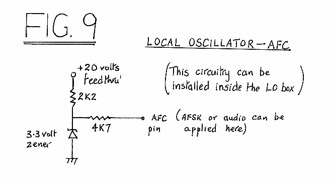
Figure 10 is an alternative circuit, used by Roger, G4PMK, and is highly recommended as a means of adjusting the offset frequency against a suitable marker signal. The ten-turn potentiometer is brought out to the from panel of the transverter housing.
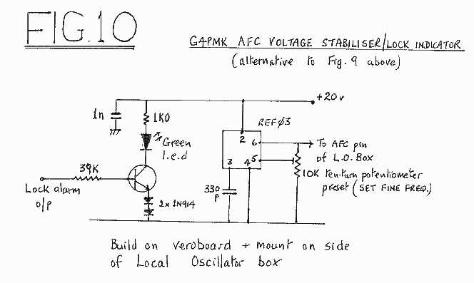
The circuit of Fig 10 can be constructed on a small piece of pc board or Veroboard and fixed to the external wall of the oscillator box. Roger's circuit allows fine frequency setting when the lids are finally replaced and the equipment is almost ready for use. The REF03 precision reference IC is a standard Maplin part.
The writer also fitted an LED indicator to show when the oscillator is in lock. Figure 11 shows the simple circuitry involved.
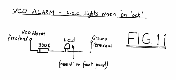
This is mounted externally on the wall of the oscillator box. When the l.e.d. is lit, the oscillator is in lock. In the writer's case, the l.e.d. was mounted on the front panel, along with l.e.d.s to indicate RX and TX states. You can double check the lock state by checking the voltage on the VCO pin. When locked the voltage is high (approx 19v) and when out of lock it is low (approx 2v).
Now refit the upper lid with one corner screw only. Identify C5, a variable tubular capacitor, not far from the crystal heater. You now need to drill a small hole in the lid (just wide enough for a trimmer tool to go through) immediately above this capacitor. Carefully mark its drilling position, remove the lid and drill the hole, taking care to de-burr it and remove all traces of metal dust from the lid. Now refit the lid securely with all fourteen screws. The hole you have just drilled enables adjustment of the crystal oscillator for accurate frequency setting . It can be covered afterwards with adhesive, metallised tape.
Turn the oscillator box over and remove the lower lid. Turn it around so that the semi-rigid coaxial line is on your left. Beneath the line is a pcb containing the phase-locking circuitry. The final, x6, multiplier to 10GHz is housed in the small box in the top right corner. Figure 12 shows the essential detail of this part of the oscillator unit. Look carefully between the wall of the x6 multiplier and the inside wall of the main box. You will see TWO small adjusting screws, complete with locknuts. Do not touch these just yet but very carefully drill two 4mm diameter holes through the main oscillator box wall, in line with each of the adjusting screws. You will need to access these screws with an adjusting tool and miniature spanner, so make sure the holes are exactly positioned!
Adjustment of the oscillator requires patience and a 10GHz frequency counter and/or spectrum analyser and a power meter. The 10GHz counter is highly desirable but the writer at first listened for a 10224MHz signal with his now-redundant wideband receiver. Connect the counter or analyser to the LO output socket on the oscillator box, via a suitable attenuator. The LO output is some 50 mW or so when finally adjusted so choose an appropriate value to protect the test equipment! On applying 20 volts dc to the oscillator you might be lucky and get a 10224MHz signal right away. The chances are you won't! Ensure that the 106.5MHz oscillator is running and that its 16th harmonic at 1704MHz is to be found. Adjustment of the tubular trimmer C5 (via the hole in the top lid) should bring it onto frequency. Don't worry about extreme accuracy for the present. Fine tuning can be done when other adjustments have been made to the multiplier.
Look for the 1700MHz free-running oscillator. This also needs to be tuned to 1704MHz, to lock it to the crystal source. If it will not tune around this frequency you will need to experiment with the tiny tuning "pads" found on the pcb stripline circuit in the bottom half of the oscillator box. These pads are very obvious.....just left of centre, next to the small diode and rf choke. Carefully short one pad to its neighbour and check the frequency. You will need to do this several times, sometimes removing the solder you just added! When you have the VCO at 1704MHz, try adjusting R20 (found in the upper section of the oscillator box). Careful adjustment of this should turn on the LOCK L.E.D (if it is not already lit) and you are now in business!
Now turn to the final multiplier. There are three adjusting screws, one on the side facing the pcb and two on the side facing the inner wall of the oscillator box (the ones you have drilled two holes for access). Adjust the screws one at a time for maximum output at 10224MHz. You should obtain at least 40mW. The more the merrier.....some constructors have achieved 75mW or more.
The writer found that, after these modifications, there was a slight
difference in frequency between transmit and receive. This was traced to
a very small shift in the voltage feeding the crystal oscillator transistor,
particularly when the 12 volt portable battery was getting low after extended
use. A complete cure was achieved by stabilising the voltage on this transistor
(Q1, 2N5179 in Figure 4) at 15 volts, using a three-terminal regulator
(eg 7815) inserted in the 20v supply between the 100 ohm resistor and the
positive end of C1. The regulator will need appropriate decoupling capacitors
at both input and output pins. No heatsinking was required. The writer
installed the regulator chip in the lower left hand corner of the upper
section of the oscillator box. If the mains psu is used, this modification
will not be required.
MODIFYING THE RF (TRANSVERTER) UNIT
Upper section
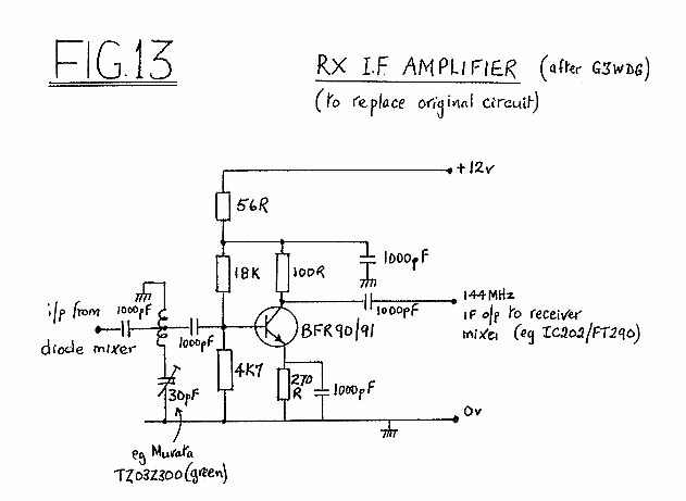
Remove the top lid of the unit. The smaller of the two p.c boards is the receive IF amplifier. It is a wideband affair and is capable of working on 144MHz but it is very wasteful of current, drawing well over 100mA! A simpler and more economical circuit is shown in Figure 13 and is actually that used in the G3WDG002 10GHz-144MHz converter (see page 18.108 of Volume 3 of the RSGB Microwave Handbook).
This new IF amplifier is constructed, "dead bug style", on a piece of single-sided p.c. board cut to the same size as the original board in the RF unit. The original board is removed as follows:
(i) carefully unsolder the white leads coming through the board to the
trimmer capacitor C1.These leads come from the mixer diodes. Since the
diodes are static sensitive, take the necessary precautions when making
this disconnection.
(ii) unsolder the IF output, the +12v and ground connections
from the board
(iii) remove the two screws holding the board to the box.
The board can now be removed and the replacement IF board fitted, using the same mounting holes of course. The new board should also have a suitable hole drilled for the mixer diode leads.
The RX IF output socket can be removed and replaced with, say, a BNC type if a suitable matching connector is not available.
Now examine the larger p.c.board in this upper section. The TX IF IN socket can be replaced with a BNC if required. 144MHz at only approximately -3dBm is needed here if the existing modamps that feed the TX mixer are to be retained. The writer dispensed with all three modamps (clearly visible near the TX IF IN socket and labelled on the board as U3, U4 and U5) so that 100mW could fed into the socket and dropped to a lower level ( around 20-30mW) via a miniature variable attenuator that was conveniently found in the junkbox ( a fixed resistive attenuator could be used instead but the variable one allows fine adjustment of 144MHz drive to the 10GHz mixer diodes). The modamps were disconnected by snipping out the multi-hole, RFC ferrite choke labelled Z4 on the p.c.board. This effectively removes the DC supply to the modamps.
The 100mW 144MHz signal was obtained by modifying an IC202S 2m transceiver to produce that amount of power. If you use an unmodified transceiver a suitable external attenuator will be required for transmit. On receive the external attenuator will have to switched out of circuit.
C27 and C28 are then removed by cutting their leads. The attenuated 144MHz RF is taken directly to the TX mixer diodes via a suitable blocking capacitor (essential where a DC control voltage is present on the 2 metre rig's output, as in the case of the IC202 for example). One could feed in 144MHz RF at the junction of R49 and R50 where about 8dBm is required for saturation. The writer found it easier to modify his IC202S 2 metre transceiver to give 100mW out and then feed the mixer diodes via a 20dB variable pad which he mounted inside the RF unit, just by the TX input socket. The attenuator is carefully adjusted on CW for a point where the 10GHz output just starts to fall off as the 144MHz RF is backed off from maximum input. A fixed resistive attennuator could easily then be soldered into the unit of course. More on this will be found in the ALIGNMENT PROCEDURE section.
Now replace the top lid and access the lower section by removing the bottom lid.
The modifications now taken on a more serious nature but they are by no means difficult. Please remember to take anti-static damage precautions when working on this section of the unit. Refer once again to Figures 2 and 3 to familiarise yourself with the layout.
Since the unit does not have a receive preamplifier you will need to decide whether or not to use it as it stands or carry out the following modifications. If you use it in its original state you will have to accept a noise figure that is in double figures. In any case it is desirable to remove the RX 6-pole filter and replace it with a less lossy type. The filter is taken out by first removing the four fixing screws at each corner of the filter unit and then very carefully unsoldering the connections the small ferrite circulators seen to both right and left of the filter. Use minimal heat here; do not damage the circulators! A useful space is now left and it is tempting to think a GaAsFET preamp could be fitted in place of the filter. The writer felt that this was an impracticable course to follow as an image rejection filter would still have to be fitted.
Receive filter replacement: The original 6 pole filter has quite a high insertion loss (around 4dB or so) and it was decided to replace it with a less lossy 3 pole version, thus allowing a two stage GaAsFET preamp (17dB gain) to be placed ahead of it and perform well.
The 3 pole filter is fabricated from the 4-pole TX filter that presently occupies the milled cavity between the TX PA and the Power monitor (see Figure 2). It is not necessary to retain a filter at the output of the PA and so it is removed in much the same way as the RX one, again being extra careful to avoid damage to the delicate stripline connections to the circulator/isolator at the power monitor and to the TX PA output. The "lossy" rubber found bridging the gaps in the cavity wall should be retained for replacement later. In addition, the coaxial output probes on the filter should also be kept intact.
The TX filter just removed is cut down to a three-section one as shown in Figure 14.
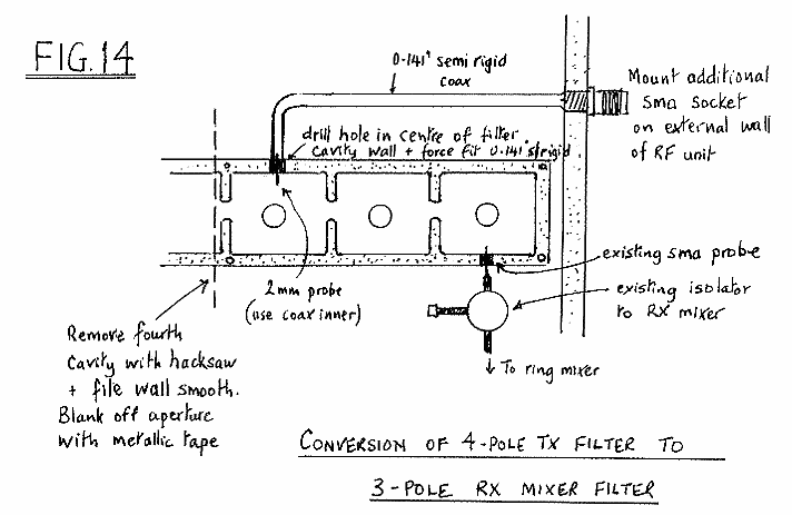
A semi-rigid coax/sma output already exists at one end of the filter. You will need to provide a similar output at the other end of the filter but on the opposite wall to the first one. Figure 14 shows the layout. The new hole should be only just wide enough to enable a short length of 0.141" (3.4mm) semi-rigid coax to be force-fitted to it so that the inner conductor of the semi-rigid extends some 2 mm into the filter cavity. The semi-rigid is fabricated as shown in Figure 14 but do not fit it just yet!
Replace the cut-down lid of the modified filter which is then mounted in the space vacated by the 6-pole RX filter. One of the original fixing screws can still be used to hold the new filter in place next to the RX mixer isolator. The other mounting hole is made by widening the smaller hole at the other end of the filter wall. Once it is mounted you should find that one of the filter output pins matches up against the ferrite isolator that feeds the input to the RX mixer. Do not solder this connection just yet. Instead imagine a short length of semi-rigid coax coming from the other end of the filter to a new sma socket mounted on the exterior wall of the RF unit, to the left of the existing coaxial output from the circulator (this was formerly where a coax to waveguide transition was fitted in the original unit). This new RX input, coax socket should be fitted on the exterior wall of the RF unit so that the short length of 0.141" semi-rigid to be fitted can connect the socket to the modified RX filter. These modifications allow an external receive preamp to be fitted at a later time if required.
Now turn to the space vacated by the TX output filter. Using a short length of semi-rigid coax, make a "jumper lead" to connect the PA output strip line with the input line of the power monitor. The writer first made a small, brass (copper will do) L-section bracket some 65mm long with L section 18mm x 10 mm. The 10mm width is drilled so that the existing filter mounting holds in the vacant cavity can be used to firmly hold the bracket hard up against the cavity wall on the side where the strip lines are located. The semi-rigid coax jumper is then fitted to this bracket so that short probes pass through holes and onto the strip lines where they are carefully soldered into place. The outer of the coax is firmly soldered to the bracket on the side facing into the cavity. The bracket now efficiently acts as a ground for the jumper lead and as a shield for the cavity. It is wise to refit the "lossy" rubber across the two gaps in the cavity wall (at the PA output and power monitor input).
Other constructors have taken the transmit output directly to the rear wall of the milled box, ignoring the jumper lead to the power monitor. However the writer believes the power monitor is too valuable feature to lose!
The physical modifications to the RF unit are now complete and it is
time to tune up the whole assembly.....
ALIGNMENT PROCEDURE
The following basic alignment equipment is required:
* signal source on 10368 MHz (could be a redundant wideband gunn oscillator)
* a 144.250MHz signal source of around 100mW, variable.
* microwave power meter (good to at least 500 mW at 10.5 GHz).
* miniature spanners to fit locknuts on the filters (6BA)
* a small allen key to fit filter adjusting
screws
PRELIMINARY SETTING-UP
TX POST-MIXER FILTER ALIGNMENT
* The following adjustments are made much easier if a 10GHz spectrum analyser is available*
Before adjusting this filter (the one situated between the TX mixer
and the TX RF amplifier stages), loosen the hex nuts and turn all
screws a half-turn clockwise, otherwise you may unwittingly tune the filter
to the image frequency. Switch on the 144.250 MHz source, starting with
a low level of output and increasing it until some indication of RF on
the 10GHz power meter is seen. Set the range on the power meter to keep
the indication in the upper half of the scale.The filter is adjusted for
maximum indication on the power meter by adjusting the filter resonators
first followed by the aperture screw. The latter is the middle screw on
the TX mixer filter. Be careful to tune the required frequency and not
the image. You may find there are two peaks with the screw adjustments.
Choose the one with the screws at their upper setting, i.e. furthest out.
This filter has a 3dB bandwidth of approximately 80 MHz centred at
10368.250MHz. If you have modified the 144MHz TX input for direct feed
to the mixer diodes, no further TX adjustments are needed. If you have
retained one or more of the modamps in the TX IF chain then L4 (near the
modamps) may need tuning for maximum drive to the diodes.
By now you should have a healthy output of over 150 milliwatts at 10368.250
MHz. If not you should first check the output of the Local Oscillator,
which should be giving around 50 milliwatts. That being in order, you may
like to coax a little more output from the GaAsFET RF amplifiers. This
is a critical procedure and fraught with problems if you are not sure of
yourself. It is vital that anti-static precautions are observed
if damage to the expensive FETs is to be avoided. The required procedure
will not be described in this paper since the aim of the writer is to get
you to put a "white box" on the air with minimum fuss. Full details of
this more advanced aligment can be found in the excellent article
by WA6CGR "A Complete X-Band SSB Portable Communications System" (ie how
to modify a "White Box") in the ARRL's Microwave Update '91, pages 206-225.
RECEIVE IF ALIGNMENT
This is a very straightforward affair. First, remove the +12 volt supply from the TX feedthrough and temporarily solder it to the RX feedthrough to the right of the RX IF OUT socket. Leave the -5v connected to its feedthrough. The Local Oscillator should be left running and connected to the RF unit.
Turn to the modified RX filter you fitted according to the details shown
earlier. This filter is adjusted in much the same way as the TX filter,
i.e turn all screws clockwise by half a turn and then adjust the resonator
screws followed by the aperture screws. The resonator screws, counting
from either end of the filter are nos. 1, 3 and 5, the aperture screws
therefore being nos. 2 and 4. Feed in, via the newly-fitted RX sma input
socket, a low-level signal at 10368.250 MHz. The writer used a calibrated
signal generator but any low-level source can be used, even a Gunn device,
provided suitable attenuation is provided. Use the weakest signal possible
so that accurate peaking of the filter screws can be achieved. If you have
access to noise figure measurement equipment you ought to obtain a figure
of around 11 to 12dB. Remember that this high NF is due to there being
no preamplifier in front of the mixer.
This completes the basic alignment of the "White Box"
PRODUCING A WORKING SYSTEM
Before it can be used as a tranverter you will need to install a suitable TX/RX changeover system, a coax to waveguide transition and, most likely, a receiver preamplifier.
Two coax relays will be needed. The most important one is that used to change the 10GHz antenna from TX to RX modes. Suitable relays are available in the stalls at rallies. They usually cost anything between £35 and £45 and so are a relatively expensive item. Do not take any short-cuts with this relay or you will certainly pay for it later! Mainline Electronics, Leicester also stock them. Look for the Dynatech/U-Zinc model D1-412A20 (good to 12GHz) or the D1-413A30 (good to 18GHz). There are several equivalents (eg Transco). It is important to use sma connectors at this frequency of course. The relays mentioned above have 28 volt DC coils but happily "shift" on 20 volts or so. In the writer's case this voltage comes from the same portable psu that feeds the local oscillator. If you can find 12 volt coils so much the better! The other coaxial relay needed is a VHF type (therefore less critical) to switch the TX IF input (ie 144MHz drive) and RX IF output (ie 144MHz downconverted received signal) to the 2 metre transceiver. The writer found a small, shielded coax relay at a rally for only £1
The changeover system requires the switching to be controlled by the
PTT switch on the microphone of the 144MHz "prime mover". The writer uses
an IC202S for this purpose. This transceiver has a positive voltage on
the antenna output socket "inner" when in the receive position. When
the PTT is depressed the voltage goes to zero. This voltage is therefore
used to control the changeover system in the "White Box", using the
simple circuit shown in Figure 15. The master relay shown in the
circuit is, in turn, used to control the other relays needed for switching
the various voltages and RF in the equipment. Sequenced TX/RX changeover
is not required at these power levels. If a TWT or Qualcomm 1 Watt amplifier
are to be used then a sequenced changeover system should be used
to avoid damage to the receive preamplifier GaAsFETs. The most popular
one to use is the G3SEK circuit as published in the RSGB Microwave Handbook
Volume 3, pages 18.117 to 118.
If an FT290R is used as the 2 metre driver, the dc control voltage
at the antenna output is the opposite of the IC202....i.e. positive on
transmit and zero on receive. This will obviously affect how you
use the changeover system shown in Figure 15.
The switching required is as follows:
(a) +12 volts from TX to RX
(b) +20 volts on transmit to the 10GHz microwave coaxial relay
(c) +12 volts on transmit to the 144MHz TX input/RX output relay
(d) +12 volts on receive to the receive preamplifier
(e) TX IF in and RX IF out to be switched via a VHF type relay to the
144MHz transceiver used as the prime mover.
Remember, the +20v and the -5V are left permanently on their respective units and are not switched.
WAVEGUIDE/COAX TRANSITION:
This is essential if a waveguide dish feed is to be used. Ideally the White Box should be located as close to the dish as possible. The writer mounted the transition on the outer wall of a Pye Vanguard case used as an enclosure for the White Box transverter. (The aluminium tray that holds the local oscillator and RF unit fits the Vanguard case exactly once the VHF hardware is removed and forms an excellent waterproof housing for a portable rig). The WG16/coax transition consists of a short (3") length of WG16 with a square flange at one end and the other end blanked off with a thin brass plate. On the broad face of the guide an sma socket is mounted so that its centre pin is 5.5mm from the blanking plate and is central located on the broad face. The sma socket should have a long centre pin, cut to 6mm. A 3mm outside diameter PTFE (Teflon) sleeve was tightly fitted over the centre pin and the waveguide was drilled with a suitable hole for the thicker probe. The socket flange was soldered to the waveguide face. A short distance down from the flange, at the other end of the waveguide, three 8BA (1.5mm) matching screws were installed at 5mm spacing from each other. These are useful when feeding antennas of unknown impedance. Further details of the transition can be found in the RSGB Microwave Handbook Volume 3, page 18.12 and 13.
RECEIVE PREAMPLIFIER
The 11dB noise figure of the "barefoot" White Box makes a preamplifier
an essential add-on unit. The writer Beta-tested a G3WDG005 GaAsFET preamp
shortly after modifying his White Box. This preamp is obtainable as a kit
from the Microwave Components Service (via G4KGC, QTHR) and is heartily
recommended as a good way to improve the noise figure to around 2dB or
so. A HEMT preamp is also available from the same source. This should be
used ahead of an existing preamp as it has insufficient gain to be used
by itself in the White Box. The HEMT preamp should lower the noise figure
to almost 1dB.
Satellite LNBs are cheaply obtainable at rallies and, once modified
to LNA mode, form useful alternatives to the preamps described above.
FINALLY
The White Box is an excellent route to narrowband operation on the 10GHz band. Its output power and stability is as good as most commercial units available at the time of writing. For a modest outlay one can obtain a local oscillator and RF transverter that would have cost a great deal more when originally supplied by Microwave Associates.
In October 1994, using his White Box to a 60cm ex-satellite receiver dish, the writer has had a best DX contact of over 600km in to Germany, with S9+ reports exchanged both ways. His antenna was indoors at the time!
The modifications described in this paper do not pretend to be the definitive
answer. The writer is certain that other amateurs will have newer and better
ideas. He would be very pleased to hear of them!
REFERENCES
· RSGB Microwave Handbook (especially Volume 3)
· Proceeding of Microwave Update 91 (published by ARRL). May
be still available from them with Visa card no.
Address: American Radio Relay League, Newington, Conn., USA
, CT 06111
· RSGB Microwave Newsletter, May 1997 (article on 20 volt power
supply)
This paper was prepared by Peter Day, G3PHO, 146 Springvale Road, Sheffield S63NU, to whom further enquiries can be made either by letter or via email (mailto: g3pho@qsl.net)
The writer wishes to thank G3PYB, G8AGN, G4PMK, G3SEK and WA6CGR for
their work and publications on the "White Box". This paper contains material
from all of them.
APPENDIX
Crystal replacement:
Required for use with a 144MHz IF ... 106.5MHz, 1ppm HC36u type.
Rated for oven temperature of 70 deg Celcius.
(5ppm would be bare minimum).
When ordering from QuartzLab or Hy-Q it is suggested that the original MA/Comm crystal is sent along with the order so that they can check it for its characteristics and make a replacement with identical specifications.
Quartz crystals may also be obtained from:
Eisch-Kafka-Electronic GmbH,
Abt-Ulrich-Str.16
89079 Ulm-Gogglingen,
GERMANY
Tel: 00 49 07305 23208
email: eisch-electronic@t-online.de
Eisch supply excellent quality components with rapid service to all
parts of Europe. They accept Visa and MasterCard.
SEE YOU ON 10GHz !