| 3.4GHz(9cm)was
the band on which I made my first microwave transmissions back
in the very early 1970s. In those days the gear was based around
a 60 milliwatt output klystron, the 726A/B. How times have changed!
I have been wanting to get back on the 9cm band for many years
but it took a visit to Germany to set me off on this latest
construction project, a 15 watt portable transverter for 3.4GHz
narrowband. |
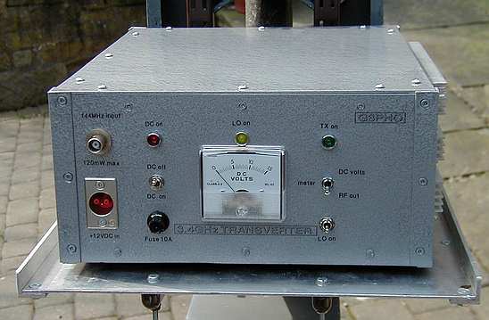
Photo above: the completed
3.4GHz transverter
The homemade aluminium
case is designed to withstand rough treatment when used under portable
conditions . Note the finned heatsink on the right hand side. This
is for the 15 watt power amplifier.
In
September 2002, I visited the VHF/UHF
Convention at Weinheim in Germany. There I purchased
a DB6NT 3.4GHz transverter kitset, direct from DB6NT himself
as he had a stand at the event. It wasn't until I got home
that I realised the construction manual was in German and
I don't know more than half a dozen words of that language!
However, all was not lost because I was well-acquainted with
Michael Kuhne's (DB6NT)
excellent kits, having already built up 10GHz and 5.7GHz DB6NT
tranverters. The following pages show you how I put the 9cm
kit together and integrated it into a potent 15 watt output
transverter. A more detailed PDF document version of this
article (with circuit diagrams, etc) is available for download
if you would like to have a copy. Just
click here to start the download. You will need Acrobat
Reader to open the document. The document is 1.3MB in size
and will take approximately 7 minutes to download with a 56K
modem.
|
Photo below: DB6NT transverter
module
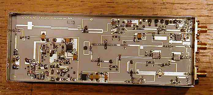
The basic module is available
in kit form from DB6NT for around £200 sterling. You can also
buy a ready made version but you'll get more satisfaction if you
build your own! The photo above shows the circuit board side with
all components finally soldered into place.
|
Just before I went
to Weinheim I had also collected a surplus solid state 9cm
PA from Mark, GM4ISM. He has been supplying these for some
time now, along with receiver sections and even antennas if
anyone wants them. The PAs come from the now defunct Ionica
telephone system which used the 3.4GHz band to relay telephone
data from base to subscribers. These excellent amplifiers
require no modification at all if one is happy with around
14 to 15 watts output. Mark and others have achieved around
22 watts out but have made some modifications, particularly
to the biassing arrangements. I am quite happy to get 15 watts
as the gear is used from portable locations, where battery
current consumption is an important factor.
|
The Ionica 15 watt solid
state power amplifier is shown below, with the lid off
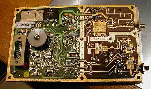
The amplifier requires
only around 1 milliwatt of drive at 3.4GHz for 15 watts output!
The input is applied to the sma connector lower right while the
output appears at the upper right connector, also sma. The 15 pin
D connector on the left is multi-purpose, receiving all power requirements
and outputting useful readings such as PA temperature and a power
output indication. The DC supply requirements are: +10V (at approx
4 amps), +12V, -12V and +5V.
|