|
3.4GHz Transverter - page 2 Tools and soldering techniques |
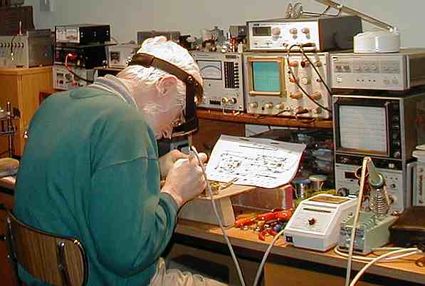
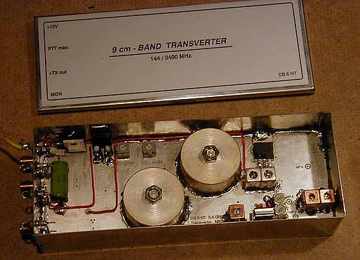
This photograph shows me at work making the basic DB6NT 3.4GHz transverter module. The kitset comes in two flat, plastic, compartmentalised boxes in which all the components are sorted and labelled. In fact, DB6NT scores 100% for presentation! A full construction manual is also provided but the constructor is expected to have some previous experience at soldering small surface mount devices (SMDs)onto pcbs, as well as sufficient knowledge about safe handling procedures in relation to static sensitive items such as the GaAsFETs and HEMTs that come with the kit. The photo also serves to illustrate some basic needs in the way of tools and other aids. Note the headband binocular magnifier that I am wearing. I find this absolutely essential! The components are often very small and it needs a steady hand to solder them in place. The extra "dimension" provided by the magnifier makes all the difference. The soldering iron I am using here is a variable temperature controlled one marketed by Vann Draper for around £60. The temperature is accurately set by the adjustable control on the front of the white base unit to my right. It's usually set to 300 degrees Celcius but can readily altered to suit particular components. The other iron is a temperature controlled Weller TCP-D type but the temperature is fixed by the type of bit used at the time.I much prefer the Vann Draper iron, which has a 0.5mm diameter bit, ideal for delicate soldering work. Other essentials include precision tweezers. Once you have had a minute surface mount component fly across your workshop after your cheap tweezers slipped you will understand what I mean about "precision"! Such items can often be found in surplus medical equipment shops and even at amateur radio rallies and "hamfests". Ideally you might use silver solder for microwave work but I have only done this at frequencies above 10GHz. Below that I use normal cored solder of about 0.5mm diameter and with a low melting point rating. I find the average desk type workbench rather low for sustained electronic construction work so I lift the work a little higher by using a small makeshift "platform" (literally two bits of wood with a 25cm x 25cm square of hardboard nailed to them!)on the workbench. This brings the project to a comfortable height where I don't get an aching neck after hours of working on it! The DB6NT kitset comes complete with a prefabricated, double-sided printed circuit board of very high quality. All connections to the groundplane side of the board from the circuit side are done via plated through holes, ensuring high stability. The construction manual (in English with export kits) should be carefully followed. Do not attempt to do your own thing! If you follow the instructions and solder carefully, your basic transverter module should work first time and should be completed in a few days. In fact my first DB6NT module, for 5.7GHz, was completed in just two days. This latest one took a little longer, five days, because I spent less time each day on it. The method I use to solder the various SMD components, such as chip resistors and capacitors and SMD transistors, involves the use of small lengths of O.5mm diameter solder that I cut off in dozens from a reel of solder before construction begins. These 1 to 2mm lengths are kept in a surplus 35mm film cassette container when not in use. I find this is a much better way of obtaining a good, neat soldered joint. To solder in a component I lightly "tin" one end of it with the iron. Then, using one of the 1mm lengths of solder, I flow a very small amount of solder onto one of the connection pads on the pcb. I then place the component on the pcb and quickly "tack" it to the presoldered connection pad, making sure the component lies absolutely flat on the pcb. Next, I lay one of the 1 to 2mm pieces of solder right up against the other end of the component, which component is gently held down with the precision tweezers I used to pick it up. The tip of the soldering iron is quickly moved along the pcb stripline towards the unsoldered end of the SMD. The small 1-2mm piece of solder quickly melts and the iron is removed, leaving a very neat joint. The other end is then reflowed to ensure a good contact. All this takes longer to describe than to actually perform! The main thing is to avoid having to pull a length of solder from a reel when fitting the components. This can result in too much solder being applied to the job. The DB6NT transverter kitset modules are housed in tinplate boxes, into which the printed circuit board is soldered BEFORE any pcb components are mounted. Before that though, the tinplate box needs to have its seams soldered and the four sma connectors and feedthrough capacitors fixed to the end wall. This requires careful measurement and accurate drilling since the pcb is soldered up to the centre spiggots of the sma connectors. It's essential to mount the board at the height stated in the manual or spurious resonances may be encouraged and/or some of the taller components, such as the silver-plated "pill box" filters, might even project higher than the edge of the box, preventing the lid from fitting! The photograph below shows the "groundplane" side of the pcb, mounted in the tinplate box. You can see that some relatively large components are fitted here .. two "pillbox" cavity filters and several helical filters, as well as a couple of standard voltage regulators, trimpots, the Local Oscillator crystal (in its heater) and a large input attenuator resistor (50 ohm). All these need a hotter iron temperature setting than the surface mount components on the other side of the board. The sma connectors are screwed to the end plate of the box. Fitting the pillbox filters is perhaps the trickiest job of the lot. It is one of the first jobs to be done after the the pcb has been soldered in to the tinplate box. There are small locating points marked on the pcb and the filters MUST be accurately located to them as each filter has two short probes coming up through the board from the circuit side. The filter must be symmetrically located with respect to them. The probes are fitted and measured acurately BEFORE the filters are finally soldered into place.
To make sure the silver-plated filters are soldered correctly I heat them up first on a kitchen hotplate! When they are too hot to touch I quickly apply 0.8mm diameter low melting point solder all around their bases to pre-tin them. Then, one by one, with the adjusting screws fully inserted in the top of each filter I lift them with a small part of pliers and I press the the cavities onto the pcb, quickly wrapping a ring of solder around their bases. My soldering iron, with a broader bit than that used for the SMDs and set at 420 degrees Celcius(its highest temperature), is then applied to the base of the filter to encourage the solder ring to flow. All this time it is essential to keep the filter absolutely firmly in place, for if you move it out of position you may have to use a small flame torch to free it later! This method usually results in quite a neat installation. The one shown above is NOT my best! Other components such as the helical filters also have to be soldered to the groundplane using a hot iron. In this case it is essential to solder quickly as you could melt the formers inside the coil housing if you applied your iron for too long. I usually cool the component down with a damp cloth, AFTER I am certain the actual solder joint has set. Once all the components have been soldered into place, I gently apply some alcohol ("Methylated Spirit") with an old toothbrush to both sides of the board to clean away any flux deposits. The module is then left overnight near a warm radiator to complete dry out. The screws are taken out of the cavity filters during this time. |