| POWER
SUPPLIES and SEQUENCER
There were two
power supplies required for this project .... the relay power supply
and the PA power supply. Both these were built on perforated, copper
clad Veroboard rather than on "one off" printed circuit
boards which are hardly worth the time etching for DC applications
such as this.
The sequencer
was purchased as a ready assembled pcb, direct from DB6NT. The very
reasonable price of this item makes home construction hardly worthwhile!
|
 The
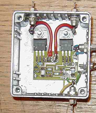
ANTENNA CHANGEOVER RELAY POWER SUPPLY The
ANTENNA CHANGEOVER RELAY POWER SUPPLY
The simple unit shown
here provides around 22 to 24V DC, easily enough to operate
Transco or Dynatech type microwave 24 -28VDC coaxial relays.
It consists of an NE555 oscillator which drives a complimentary
pair of transistors(TIP31/TIP32)into a diode pump (2 x 1N4001).
A small piece of veroboard was used to mount all the components
except for the two transistors, which are securely bolted
to the wall of the small diecast aluminium box which acts
as a heatsink. One of the transistors is fitted with an insulating
washer as its flange is above ground potential. I'm indebted
to Dave Robinson, G4FRE (WW2R)for this nice little circuit.
Once again, the circuit and full details can be found in the
PDF
document concerning this transverter project.
|
|
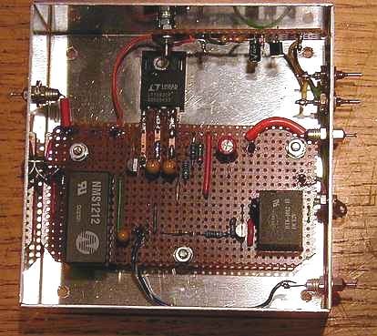 The
PA Power Supply
was also made on Veroboard and housed in an aluminium box
with all input and output connections made via feedthrough
capacitors. The supply provides nominal +10VDC, +12VDC, +5VDC
and -12VDC. The latter is produced by a DC-to-DC voltage inverter
IC, the NMS1212, shown here on the left side of the photo.
This was the only IC I could find that would produce enough
current for the -12V PA bias. The +10V supply is produced
by an LT1083CP regulator which is fed from the main +12V line
of the transverter. This chip is capable of producing much
more than the 4 or 5amps required by the PA and so is well
under-run in this application. Nevertheless it requires good
heatsinking as can be seen in the photo above. The supply
has a built in failsafe circuit to protect the PA in the event
of the -12V bias supply failing. The main +12V input is switched
to the LT1083 regulator by a relay. When the bias supply comes
on, a transistor relay driver is operated by the -12V from
the inverter. The small relay (contacts rated at 10A DC)can
be seen in the lower right of the photo and this then switches
the +12V input to the 10V regulator. Similarly the +5V supply,
which enables the PA, is only activated when the same relay
contacts are closed. The NMS1212 bias supply IC was chosen
because it supplies -12V even when the portable battery supply
drops from a fully charged state. Normal regulators need some
2 volts headroom and thus an input of almost 14 volts would
be required, not easily come by under portable conditions.
The
circuit of the PA power supply is a modified version
of one supplied by John, G3XDY, and can be recommended for
other PAs where voltages other than 12V are required at several
amps. The
PA Power Supply
was also made on Veroboard and housed in an aluminium box
with all input and output connections made via feedthrough
capacitors. The supply provides nominal +10VDC, +12VDC, +5VDC
and -12VDC. The latter is produced by a DC-to-DC voltage inverter
IC, the NMS1212, shown here on the left side of the photo.
This was the only IC I could find that would produce enough
current for the -12V PA bias. The +10V supply is produced
by an LT1083CP regulator which is fed from the main +12V line
of the transverter. This chip is capable of producing much
more than the 4 or 5amps required by the PA and so is well
under-run in this application. Nevertheless it requires good
heatsinking as can be seen in the photo above. The supply
has a built in failsafe circuit to protect the PA in the event
of the -12V bias supply failing. The main +12V input is switched
to the LT1083 regulator by a relay. When the bias supply comes
on, a transistor relay driver is operated by the -12V from
the inverter. The small relay (contacts rated at 10A DC)can
be seen in the lower right of the photo and this then switches
the +12V input to the 10V regulator. Similarly the +5V supply,
which enables the PA, is only activated when the same relay
contacts are closed. The NMS1212 bias supply IC was chosen
because it supplies -12V even when the portable battery supply
drops from a fully charged state. Normal regulators need some
2 volts headroom and thus an input of almost 14 volts would
be required, not easily come by under portable conditions.
The
circuit of the PA power supply is a modified version
of one supplied by John, G3XDY, and can be recommended for
other PAs where voltages other than 12V are required at several
amps.
|
|
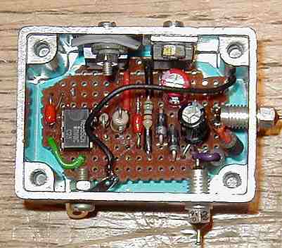
 The
Sequencer
is a DB6NT SEQ3. It can handle a PA supply of 12 volts at
18 amps, well in excess of my system! I believe in rating
components very conservatively. That way you avoid system
failure later. The sequencer comes ready made for around 25
Euro (about $25US) and is hardly worth the bother of making
it yourself. I mounted this one in a diecast aluminium box
with all supplies in/out via 1000pF feedthroughs. The sequencer
provides proper TX/RX/TX changeover protocol so that the sensitive
receiver GaAsFETS are protected from the RF damage that would
almost certainly occur if no sequencer were used. A good friend
of mine tried out his 15 watt PA 3.4GHz transverter in a contest
and blew his receiver "front end" almost immediately
... he was not using a sequencer! The
Sequencer
is a DB6NT SEQ3. It can handle a PA supply of 12 volts at
18 amps, well in excess of my system! I believe in rating
components very conservatively. That way you avoid system
failure later. The sequencer comes ready made for around 25
Euro (about $25US) and is hardly worth the bother of making
it yourself. I mounted this one in a diecast aluminium box
with all supplies in/out via 1000pF feedthroughs. The sequencer
provides proper TX/RX/TX changeover protocol so that the sensitive
receiver GaAsFETS are protected from the RF damage that would
almost certainly occur if no sequencer were used. A good friend
of mine tried out his 15 watt PA 3.4GHz transverter in a contest
and blew his receiver "front end" almost immediately
... he was not using a sequencer!
|
All supplies and the
sequencer are protected by suitably rated in-line fuses(see the
block diagram). Do not cut corners and miss out this protection
... it could be a costly mistake if you did!
|