|
3.4GHz Transverter - page 7 The Antenna System |
|
The 3.4GHz transverter would not be complete without a suitable antenna system. I already had a 1.2m (4 foot) diameter dish, which I use on 5.7GHz and 10GHz. Unfortunately I could not make a suitable feedhorn to slot into the feed mount already fitted to this dish. My 5.7 and 10GHz feedhorns do fit the mount and thus I can change bands very quickly from 3cm to 6cm ... but not 9cm! So, for 3.4GHz, I decided to make a whole new set of mounting struts and a horn mount for the dish. These could be fitted for the times when I would go out portable with the 3.4GHz system and be changed for the 5.7/10GHz struts for the times when I would activate those bands. I tried a simple log periodic feed for the 23, 13 and 9cm bands on pc board as an alternative. This did fit into the existing 10GHz mount but unfortunately it could not handle the 15 watts at 3.4GHz.
|
 This
is the completed dish feed. A commercial "chaparral"
or scalar feedhorn was on hand but the rear part of it had
a large waveguide flange. I wanted to use a circular horn
feed of the VE4MA type since this was eminently suitable for
the dish's 0.4 f/D. So I made a "soup can feed"
and arranged a simple clamp of copper strip to fix it to the
waveguide flange. The waveguide port on the diecast chaparral
horn was filed to make it into more of an elliptical cross
section, in an attempt to provide an "easier" transition
to the circular soup can section.
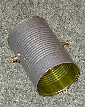
This
is the completed dish feed. A commercial "chaparral"
or scalar feedhorn was on hand but the rear part of it had
a large waveguide flange. I wanted to use a circular horn
feed of the VE4MA type since this was eminently suitable for
the dish's 0.4 f/D. So I made a "soup can feed"
and arranged a simple clamp of copper strip to fix it to the
waveguide flange. The waveguide port on the diecast chaparral
horn was filed to make it into more of an elliptical cross
section, in an attempt to provide an "easier" transition
to the circular soup can section.|
|
The soup can feedhorn
showing the position of the input sma/probe and the adjustment screw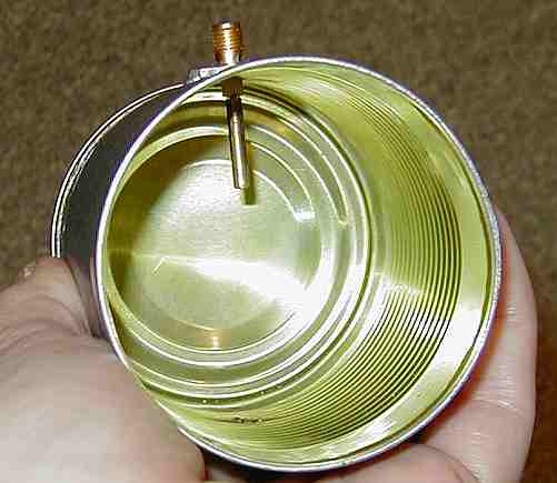 |
|
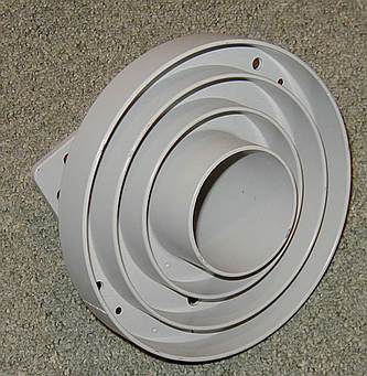
This photo shows the commercial chaparral or scalar feed. Though designed for a slightly higher frequency than 3.4GHz, it does appear to work well. |
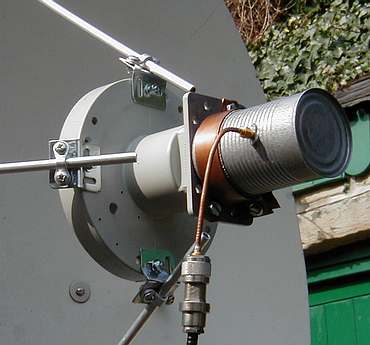
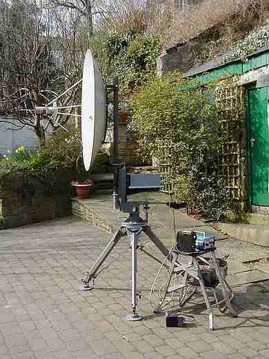
This photo shows the complete 3.4GHz antenna system on its heavy duty tripod, with the 3.4GHz transverter fitted, ready with the G4NNS Noise Amplifier for some sun noise and sky/ground noise measurements |
| RETURN TO FRONT PAGE MENU |