|
by Brian Coleman, G4NNS |
| Details of this useful item
of test equipment appear on this website by kind permission of its designer
Brian, G4NNS.
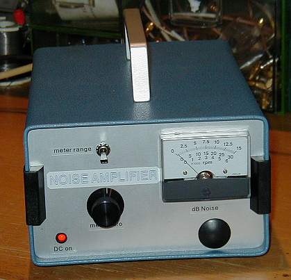
Click here for the full, constructional article in PDF (Acrobat) format. In it you will find the full text of the article that appeared in the January 2003 issue of the RSGB MIcrowave Newsletter. The example illustrated to the right and in the following photographs is that built by the webmaster, G3PHO. the nice blue case was a surplus item bought at the Weinheim (Germany) VHF/UHF Convention in September 2002. |
 |
A noise power indicator can be a useful tool for judging the performance of microwave receivers using the Y factor method (cold sky vs warm object). This relies on the fact that all bodies above absolute zero emit black body radiation which can be detected at the higher microwave frequencies. In practice this means that you can use the cold sky vs a known warm reference. Aiming the antenna at the house nearby is best and you can assume its temperature is about 293K. Measurement as opposed to indication can be accomplished by using a precision attenuator in front of the indicator and using the same level at the detector to avoid any non-linearity in the system. The system can be used to ensure that an EME antenna is tracking correctly using moon noise. Other uses of this tool can include antenna testing. It provides a more precise and easier to read system than an S-meter and can, in conjunction with a precision attenuator provide a means of making fairly precise measurements of the order of +/- 0.2dB. When using a warm source such as your house remember that it should fill the aperture of your antenna. This is why small antennas (more than about 0.5 degrees beam width) do not see the full potential sun or moon noise.
The system consists of a high gain amplifier (around 70dB) and a sensitive detector at the IF frequency (in this case 144MHz). The bandwidth needs to be as wide as possible but not exceeding that of the transverter front end. This is important as noise generated outside the desired pass band of the transverter is not relevant to the system performance and could swamp the power indication and lead to misleadingly poor indication of receiver performance. The 3dB bandwidth of this indicator is about 1MHz. Relative measurements are made by using a switched attenuator in front of the noise power indicator. Such attenuators can be found at microwave flea markets.
The next page shows photos of how G3PHO put the G4NNS noise indicator together.
GO TO THE NEXT PAGE ![]()