THE G4COM NOISE COMPARATOR
 This
unit, designed by G4COM, is a very useful "tool" for adjusting receiver
preamplier stages for optimum noise figure. It is very simple to use and
easy to make. A complete kit is available in the UK and the writer's example
shown here was built up from one of them. However, it can be made from "scratch"
at home but the nice pcb included in the kitset was too much for your scribe
to resist!
This
unit, designed by G4COM, is a very useful "tool" for adjusting receiver
preamplier stages for optimum noise figure. It is very simple to use and
easy to make. A complete kit is available in the UK and the writer's example
shown here was built up from one of them. However, it can be made from "scratch"
at home but the nice pcb included in the kitset was too much for your scribe
to resist!
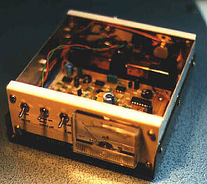
The front panel switches are (left to right): power on/off, noise on/auto/off,
full scale meter range 5dB/15dB.
The meter shows the relative noise figure of the amplifier under test.
The unit produces wideband noise across the spectrum from DC up to the high
UHF bands. Microwave noise output at 10GHz is also possible as the
unit provides a voltage to drive a microwave diode noise generator. If the
noise source output can be accurately established, then an absolute
noise figure measurement can be obtained. Most amateurs, however, are happy
enough to see relative improvements made to their receive system and can
arrange to get absolute measurements at various amateur technical gatherings
such as the regular RSGB Microwave Round Table meetings. As I said above,
this little unit will get you into the ballpark, ready for that session
on the Hewlett Packard!
The general idea of the system is to feed the audio output of the receiver
under test into the Noise Comparator while the noise generator output of
the unit is fed into the receiver rf stage. The noise figure of the receive
is a measure of the ratio between the rectified audio voltage across the
terminals of the Comparator's monitor speaker, with and without noise
generator input. Simple noise measuring devices often use manual on/off
switching of the noise generator. The G4COM noise comparator switches the
noise on and off automatically, at a rapid rate. The front panel meter indicates
the difference between the two states. Adjustments to the preamplifer under
test produce a HIGHER meter reading as the noise figure is LOWERED, indicating
a bigger difference between the constant output of the internal noise generator
and the operator-adjusted internal noise produced in the preamp itself. The
two, switched ranges (5dB and 15dB full scale) make even low noise figure
readings possible. The heavily damped meter indication is quite stable enough
to notice fractions of a dB change with
adjustments.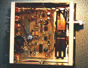 It essential to operate the receiver without AGC,
i.e. on the linear portion of its gain curve, when using this equipment.
Thus noise blankers and agc must be disabled. FM receivers must not be driven
into limiting.
It essential to operate the receiver without AGC,
i.e. on the linear portion of its gain curve, when using this equipment.
Thus noise blankers and agc must be disabled. FM receivers must not be driven
into limiting.
The switching voltage in the unit is derived from a simple astable multivibrator
operating at 30Hz, while the internal noise generator uses a transistor operated
as a diode in reverse breakdown, its dc bias voltage being controlled by
the multivibrator.
The meter reads linearly in dB across its range. The receiver under alignment
is automatically terminated at 50 ohms at its antenna input when connected
the Comparator's noise output connector.
-
Full constructional and operating details are available in the RSGB Microwave
Manual, Volume 2. Details of how to obtain this and the other two volumes
can be found at the RSGB Web Site.A kit,
including pcb, case, components, is available from the following sources:
HANDS ELECTRONICS, Tegryn, Llanfyrnach, Dyfed, SA35 0BL, Wales,
UK
Telephone: (UK) 023977 427
(It is suggested you first write "snailmail" for latest prices, shipping
charges, etc.)
OR FROM:
BADGER BOARDS, J.A.B ELECTRONIC COMPONENTS,
P.O. Box 5774, Great Barr, BIRMINGHAM, B44 8PJ,
ENGLAND
Telephone: (UK) 0121 682 7045
Fax: (UK) 0121 681 1329
 RETURN TO SIMPLE TEST GEAR INTRODUCTION
RETURN TO DRAKE DOWNCONVERTER NOTES
RETURN TO FRONT PAGE