(PLUS IDEAS FOR TERRESTRIAL USE)
HAVE YOU GOT ONE OF THESE LITTLE BEAUTIES?
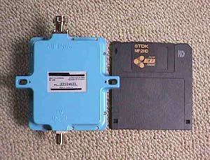
The module on the right is a Drake 2880 microwave downconverter designed for TV distribution service at 2.4 to 2.7GHz. It is ideal for use as a 2.4GHz receiver front end for the amateur satellite service. It is very compact (the size of a 3.5inch floppy diskette!) and with very little modification can readily be used at masthead, with a suitable antenna (yagi or dish), to receive various satellites including Phase 3D when it is launched in 1998.
A great number of the modules have been available in the USA but they originally come from Japan and retail at around $25 US over there. You could not make one for the price!
The information that follows is to help you receive the 2.3-2.4GHz band with one of these modules.
Full modification details for use with P3D can be found at the website
of Masa, JN1GKZ, at the following URL:
http://www.din.or.jp/~m-arai/sband/convmode.htm
PLEASE NOTE: Masa does not supply the Drake modules so please do not ask him!
When you have visited Masa's excellent pages please return to these pages to download the following useful notes, written by Larry Filby, K1LPS. Larry has spent some interesting moments with the downconverter and his observations are invaluable to anyone who has one.
Our very grateful thanks go to Larry (and to Masa for the photos)....
Read on....
THOUGHTS AND IDEAS ON THE DRAKE 2880 2.4GHz
DOWNCONVERTER
(A summary of postings to the Internet VHF Reflector by Larry Filby, K1LPS)
<k1lps@plainfield.bypass.com>
Having just finished up a week or two of playing with the Drake 2880 MMDS downconverter, which was featured in the February '98 QST I thought it was time to pass along what I found out about this unit.
The Mode S application was of little interest to me at this point but I did wonder how the unit might perform down at the weak signal end, 2304.1MHz, and how I might achieve the performance that weak signal operators are used to on that frequency, i.e. 1 to 1.5dB noise figure or less. If you plan to use your Drake for 2.4GHz satellite work, you may not need this sort of performance, 3 to 4dB being achieved with the simple modifications, change of crystal and maybe a preamp.
My approach does, however, require appropriate test equipment and experience, for evaluation.
I ordered two units from a supplier, (SCTV-SkyCable, $39, shipped) who furnished some information not seen in the QST article.
Experiences with unit 1:
Basic modifications:
 I made the recommended basic modifications of removing
the red coils and associated chip caps and I also removed the choke that
supplies power to the unit via the "F" connector and fed the voltage directly
to the + side of the polarity/transient protection diode. A small hole was
drilled just to the right of the F connector to pass the supply lead. Be
VERY careful drilling this hole and don't go too far or you could
destroy components on the board.
I made the recommended basic modifications of removing
the red coils and associated chip caps and I also removed the choke that
supplies power to the unit via the "F" connector and fed the voltage directly
to the + side of the polarity/transient protection diode. A small hole was
drilled just to the right of the F connector to pass the supply lead. Be
VERY careful drilling this hole and don't go too far or you could
destroy components on the board.
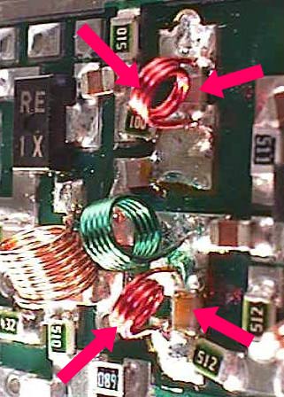
The removal of the two red coils and chip caps (see photo left) opens up the post amplifier response so that you can use IFs as low as 144MHz. You perhaps need not do these mods if you wish to use IFs above 222MHz.
According to my supplier, the crystal is spec'd for 15 pf capacitance, not 25 pf as stated in the QST article. Unfortunately I'd already ordered the crystals from ICM ! The load capacity specs affect final frequency range. A 25pF crystal will be 200kHz high on 2.1GHz.
The notes supplied to me state that if you wanted to run L.O. below 2100 MHz you need to pad the chip cap at the end of the VCO tuned line (a value of 3 pf was suggested) the implication being that running at 2160 and below was possible.
The Part Number from ICM is 433492. This is for an FM-5 holder (Small), High Accuracy (10 ppm), and 15 pF load capacity. The FM-5 holder is actually smaller than the original but the wire leads fit fine, the crystal does not interfere with the installation of the cover and the netting trimmer is accessible.
The crystal was installed, the post amp mods were made for better performance at 144MHz I.F., and the VCO locked up without any problem. The stability of the L.O. at 2160 was excellent at room temperature and didn't seem to be particularly sensitive to cool drafts without the cover on. At 2160MHz, the frequency only moved 1 kHz in the first hour and remained within a few hundred Hz the rest of the day. (Someone asked me what the VCO test point measured....I don't know. The thing worked and I left it at that.)
Frequency accuracy is not good for the perfectionist... but may have been the result of the wrong load capacity. I don't plan to spend another $20 to find out! As it was, the frequency was adjustable plus and minus around 2160.2MHz so I settled for that as a nice round number.
The long range plan here was not only to see how this thing would work at 2304MHz but if it could be turned into a full blow transverter. Initial tests doing a rough tap of L.O out of the VCO indicated plenty of signal. An SMA connector and probe made of UT-085 was installed. More on this later.
Improving the Noise Figure at 2304MHz:
The next step was to see how the receiver was going to perform at the 2304 frequency. Noting the noise figure specifications given in Table 1 on page 44 in the February 1998 QST article and that it seem to imply no mods were made to the first RF stage, the question of performance at 2304 MHz is left largely unanswered.
My unit was then interfaced to the noise figure meter. Initially the results were VERY poor..... plenty of gain to light up the green light but a noise figure around 15dB or so. My first suspicion was the interdigital PC filter. Bingo! But contrary to how I figured... the input microstrip was the one that solved the problem. To make a long story short, it was found that three things improved the noise figure at 2304MHz:
I used pieces of gold plated, flat device lead, cut from a microwave diode, to make the line extension and stub. The first mod of the three listed above has the most dramatic effect on the noise figure performance and it is relatively easy to do. The others give a half to one dB improvement each. Considering that even an 8 to 10dB basic NF will be covered by a good preamp you may feel the second and third mods are not needed. The other elements of the filter didn't have enough effect to bother with, and no other spots were found that improved the performance. It is not red hot for something with an LNA stage ahead of the mixer but at least it works. At no point, under any conditions, did I ever see any signs of instability.
All of this was without any covers on anything. Considerable time was spent backtracking, because any attempt to put the subcover, or the main cover, singly, or in combination, resulted in a degradation in NF.
All these mods assume access to a noise figure meter.
To make a long story short... 7 dB NF... all buttoned up, all covers in place.
Having no signal generator or weak signal source for 2304, I fired this thing up into the FT290R.I used a signal generator to put the third subharmonic (768.03 MHz) into the unit and immediately found an S9+20 signal, dead on frequency. My 'quick take' on listening to the system is that it probably has too much post amp gain and the addition of another preamp stage may further aggravate the situation ... but that remains to be seen.
Phase noise? ....don't know. I can't vouch for the purity of the synthesized signal generator. The signal sounded a wee bit rough but it may well be the generator. I'll check later with a known clean source.
The system is far more stable than many of the 10GHz systems I've dealt with. I intend to run a preamp anyway, but the system probably wouldn't do too badly as-is. More on preamps later.
Probing with my finger in that area had no effect on the NF reading.
And speaking of filtering: I observed the L.O. on the spectrum analyzer...the nearest spurs were 150MHz away and down -30dB.
Preamps:
Use your favorite....I have an MGF1302 unit, not yet operational and tested. There are numerous, published, homebrew designs and kits (some built up) available from suppliers such as DownEast Microwave. A very simple, effective and inexpensive solution is to use external LNA units available from the MMDS industry. These are made to mate with the downconverters and achieve gains of around 15dB with NFs of around 1 to 1.5dB. They are available in the U.S at around $25 - $34.
We are talking "plug 'n play" here ... no building, testing and packaging!
Two preamps that have been used are the California Amplifier #30947 and the Conifer PA1033. They are spec'd from 2100-2700MHz and bolt right up to the Drake N connector and operate from +12v just fine.
Various suppliers have the 2880 from $25 to $39. These things are tiny...so hope you have some good eyes and a steady hand.
There is a web site in Japan with info on these units, where they are manufactured for Drake.
http://www.din.or.jp/~m-arai/sband/convmode.htm
There are pretty good colour pictures and instructions to convert these units...all oriented toward Mode S at 2400 MHz.
Other I.F.'s:
The JA operating the website is using 433 MHz as an I.F. However, there is some confusion because he says the VCO won't tune down to the 1967 MHz area without modification. I couldn't find any details of his suggestions in that regard. The statements in the notes provided by my supplier indicated padding the VCO for frequencies below 2100, so I'm presuming it can be done. Higher I.F.'s may yield better basic performance than what I'm seeing with my system at 2 metres. I leave that up to someone else to deal with.
And now for unit number 2!
I completed a lot of work and testing on the #2 unit and it ended up being pretty much "butchered"... but still working. WB5OHH reported getting yet a better N.F. out of the basic unit by replacing the front end input PC loop with a loop of wire and then manipulating that loop of wire for best NF. My advice? Don't do it! Yes... after considerable struggle I did see as little as <3 dB N.F. But... there seemed to be evidence of possible slight instability in the LNA stage... and I was back to having the N.F. drop off to poor with the sub-cover on. In the end I was able to get a stable 4 dB with just the outer cover on. My opinion is that it is a waste of time trying to get the N.F. down to less than 6 dB... which is easy to do. What I did do on the #1 unit, was to cut out the tiny little trace that effectively shortened that input hairpin loop and that yielded a 1 dB improvement in N.F... down to 6 dB... all covers in place. This stuff is tiny, so good luck. I used a razor blade to scrape out that little shorting trace.
General comments
High IF Noise level:
In the meantime, I'll be trying various preamps and see what improvement can be made in the receiver and start on the transmit stages......
Precautions needed:
Be very careful when removing the boards from the case. Be especially careful when removing the input/output connectors. Also be very careful in re-assembling. The "N" connector is easiest, but be careful not to break or disturb the input blocking ceramic capacitor. Make sure that the mounting screws are tight on the "N' connector before re-soldering. The traces on input and output are easily damaged. To remove the "F" connector wick away as much solder as possible... loosen the "F" connector slightly with its nut... and then withdraw it carefully. You probably won't be able to wick out all the solder and need to apply judicious heat as you withdraw the connector to clear the board. Bulkhead type BNC connectors will screw into the same hole, although on some types, the threaded section is too long. The center pin of a BNC is too large to clear the board so you'll have to jumper from the cut off center pin to the board. (No... I have nothing against "F" connectors... but have changed all of mine to BNC.)
Power supply:
Note also, that the power supply range of these units is 13-24 volts DC. One test I always run when doing N.F. measurements is to vary the power supply voltage, up and down. If one was planning to run this thing off a battery in portable operation, deteriorating voltage does have some effect on the basic N.F. of the converter. However, with a good preamp ahead of it all, this effect should be minimal. If you really insist on a stable basic N.F., and are running from AC mains, run more supply voltage. (i.e 18-24 volts). I still don't have a preamp going but I'm confident that anything down to 10V will work for my purposes, even though that is somewhat below the "headroom" for a conventional 10V three terminal regulator.
Other applications for the Drake 2880
I'm looking at some other applications for the VCO/PLL portion of these units. If you look at the QST article you'll note that the board could be cut in half very easily, if you wanted to use the VCO/PLL for some other application. I'm hoping the supply of these things doesn't dry up, as I see a lot of potential here.
Possible transverter use:
Having finished testing the receiver, the L.O. tap was measured and came out to -15 dBm. A couple of MMIC's will solve that problem and maybe some filtering at 2160. The L.O. tap is a short (1/2") of bared UT-085 as a probe placed above the microstrip line to the mixer. .
I've experimented with various tap-offs for transmit L.O. My latest one yielded -5 dBm... and I ended up backing it off to -10 dBm. My UT-085 is brought in between the two regulator IC's... routed over the supply end of the protection diode with the end in-line with the trace that goes up to the mixer. I then used a piece of insulated wire from the UT-085 down to the ground connection near the lower wall. I ended up just soldering the cold end directly to the ground trace. I tried terminating it with a 50 ohm chip resistor but had mechanical problems and abandoned that. Adjust the height of the pickup line for desired output. Coupling as much as -5 dBm out had no effect on receive sensitivity. I will likely refine this further once I start working with the MMIC amp/filter portion. Space is tight in this thing... so the UT-085 works out fine. UT-141 would probably be too large and difficult to manipulate around parts inside. I was fortunate to have some surplus UT-085 lengths with a two-hole SMA on one end. You could use RG174 or similar subminiature coax, and no connector at all.
SOURCES
I'm not hearing much about new sources for the 2880. The Comnet source in CO may have dried up. I checked some others who would only sell to wireless cable companies. At my last check, SCTV-Skycable (WB5OHH) in CA still has them at $39, or 3/$100, PPD, and also has a preamp rated at 1 dB/20 dB gain, for $34 PPD. Bob has a lot of experience with these 2880s and provides excellent service. He can be contacted at <the.partains@worldnet.att.net> for information and terms. His telephone number is: (818) 973-3118 or by "snailmail" at:
4804 Laurel Canyon Blvd-#533, Valley Village, CA 91607, USA
SCTV-Skycable also has a website now at: http://www.nitehawk.com/sctv-skycable/
Wireless cable doesn't seem to be doing well in a lot of areas for various reasons. It may signal a lot of this MMDS stuff coming onto the surplus market in the near future. Perhaps there are other brands/systems that could be converted to ham applications. As it stands now I'm very happy with the overall performance of the receive portion of the Drake unit at 2304 with 2m I.F... and there is more improvement coming I'm sure. I'm starting to put together the transmit side now, and will pass along that info when I have it working.
I've got more of these units on the way... and will continue to experiment with them.
It's been a fun project so far, and shows great promise as an inexpensive way to get on 2304. The entire system should be very small, and could make a good rover system. I hope this information may be of some use to those playing with these units.
Onward and upward!
CUL.
73 from Larry (K1LPS/Vermont)
Since the notes above were compiled by Larry, some further work has been done in the UK by David Bowman, G0MRF. His experiments have resulted in noise figures below 3dB being achieved with the Drake unit at 2400MHz. Click on the icon below to get full details of these new modifications............