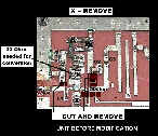
 Click on this photo for a look at the pcb beforemodification
At the Amsat-UK colloquium, held over the last weekend of July, 1998, the most popular module presented to the RSGB microwave committee testing team was the Drake 2880 downconverter.
The converters tested were either original and unmodified or had been modified for 2400MHz to 144MHz reception using the information published in Japan and reprinted by Amsat QST and others. During the course of this three day event at the University of Surrey, it became clear that an extra few minutes work could provide a considerable improvement on the original conversion performance.
LOCAL OSCILLATOR
A Drake 2880 conversion typically involves changing the local oscillator crystal to 8.81250 MHz Any crystal manufactured should be specified for parallel operation with a 15pF load capacitance. An HC18/T will fit perfectly.This is a reduced height version of the standard HC18U. Standard HC18 or HC49 crystals will not fit in the space provided.
I.F. AMPLIFIER
The original I.F. circuit includes two amplifiers coupled via a 3 stage bandpass filter. As the Drake bandpass filter is centred on 300 MHz, changes to the I.F. are essential if the modified units are going to perform adequately at 144MHz. The published modification is to remove two coils and two capacitors. Looking at the circuit these components form two parallel tuned circuits between the signal path and RF ground. Removing them certainly improves the performance. However, tests with a microwave sweep generator showed that the performance at 144MHz was still around 10dB down on that at 300MHz.
Click on this photo for a look at the pcb beforemodification
Looking closely at the circuit,
we found a green coil in the middleof the IF section of the board. This
has two chip capacitors, one eitherside of it, and together they form a
series tuned circuit at the original I.F. of 300MHz. By adding a
22pF capacitor in parallel with each of these two chip caps the resonant
frequency can be reduced closer to 144MHz.The following typical improvements
were measured.
| ORIGINAL CONVERSION | ADDITION OF 2 x 22pF | IMPROVEMENT | |
| Noise Figure |
|
|
|
| Gain |
|
|
|
All of the converters modified in this way gave improved performance. The capacitors used were wire ended ceramics. A sweep of the I.F. also showed an improved curve with less passband ripple.
NOISE FIGURE
The system noise figure is determined mainly by the front end GaAsFET and the insertion loss of the three stage stripline image filter.
The system noise figure measured throughout the three day period ranged from 5dB to 8dB. Further testing produced two possible methods of improvement.
(1) BANDPASS FILTER
The three section filter is optimised for 2.55GHz and is beginning to role off at 2400MHz. One unit was selected and the lines were extended by soldering short lengths of 22 SWG tinned copper wire to the foil. The wire was cut to approximately 3mm and soldered to the end of the lines. The total extension to the lines measured between 1.5 and 2mm. Do not use lengths longer than this as image rejection will be degraded. Use minimum solder.
This modification will reduce noise figure by up to 1dB and will bring the unit close to its claimed performance
(2) LOW NOISE AMP
If there is to be a further, and substantial, improvement in noise figure then the front end GaAs FET should be replaced with a higher performance device. Adding mod amps after the GaAs FET does not have a significant effect.
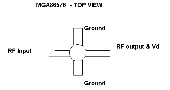
I chose to replace the device with a Hewlett Packard MGA86576. This modamp is based on GaAs PHEMT technology, is specified to 6GHz and has an internal bias supply and matching circuits. It also fits onto the pads vacated by the Drake GaAs FET and costs around £4.00!
This modification should only be tackled by the experienced constructor.
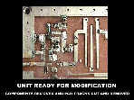 Clickon this photo see the pcb ready for the modifications
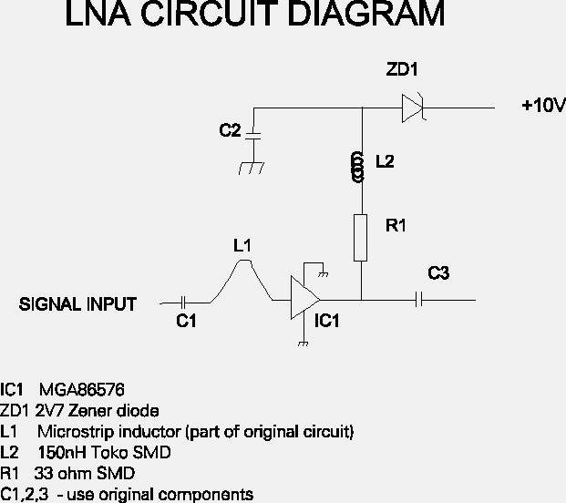
The circuit below shows the modified RF stage:
1) Identify the amplifier input and output coupling capacitors on the existing GaAsFET circuit. These should be left in place.
2) Remove the FET and the surrounding components. Retain the 33 Ohm chip resistor.
3) Locate the thin track which is connected to the drain circuit. It ends just under the first element of the image filter. Cut this at the drain end and remove a 3-5mm section to prevent interaction.
4) Remove PCB and locate yellow wire on underside which supplies +5Vt o the LNA. Desolder and remove.
5) Drill two 1mm holes for earthing the ground connections of the MGA86576. Fit two 1mm Pins from the top of the PCB. Use the device to ensure correct placement. The body of the IC should fit between the heads of the pins.Turn the board over and solder the pins to the ground plane. Cut short.
Note: Other methods of earthing will work and may be improved e.g. a cut in the PCB and use wrap round foil. The existing plated through holes however are too far from the device to be effective.
6) Fit an insulated wire link from 10 Volt regulator to LNA supply pad (4 above.) This should run along in the existing cast channels. Mount PCB in enclosure ensuring it lies flat
7) Fit MGA86576. Solder 33 Ohm close to output lead. solder SM inductor to 33 OHM. Fit decoupling capacitor to ground. Finally fit 2.7V zener from inductor to 10V supply.
![]() Click on this photograph which shows the RF stage after modification.
Click on this photograph which shows the RF stage after modification.
Compare it to your own, unmodified version to locate the changes and new components
8) Apply power to module. Correct operation of the LNA can be determined by measuring voltage drop across the 33 Ohm. The correct current is 13-15mA. Never short the 86576 input terminal to ground as this will remove the bias and destroy the device.
| CONVERSION GAIN
|
dB |
|
| ORIGINAL MODS |
|
|
| ADD 22pF to IF STAGE |
|
|
| CHANGE RF STAGE TO MGA86576 |
|
|
| EXTEND IMAGE FILTER |
|
|
| Allowing
for VAT, delivery to me and onward shipping I can supply the
MGA86576, 150nH inductor Zener diode and 1mm pins for cost price at £7.50 David Bowman G0MRF. g0mrf@aol.com 38 Wyndham Crescent, Hounslow, Middlesex TW4 5HZ, United Kingdom. |
WEBMASTER'S COMMENTS:
Many thanks indeed to David for allowing us to post these most interesting and useful details on this website.
![]() RETURN TO EARLIER DRAKE MODIFICATION DETAILS
RETURN TO EARLIER DRAKE MODIFICATION DETAILS