Part 1
(photo courtesy of W0EOM)
(photo courtesy of W0EOM)
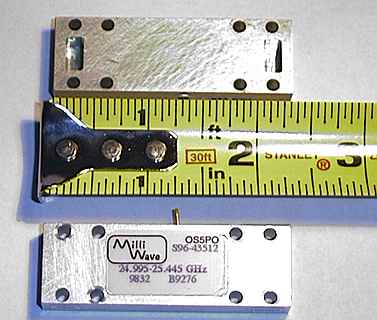
In January 2001, through the good nature of Will Jensby, W0EOM, a fairly large quantity of state-of-the art 24GHz RF power amplifiers became available for amateur use (and at a very moderate cost!). The original specifications indicated a possible output of some 800 milliwatts or so for an input of around 80 microwatts ... all of this from a module 2.25 inches long and around half an inch thick! Although the modules were originally spec'd for just outside the amateur band, Will had already found that they gave considerable output on 24.192GHz. These very small modules were just what those of us on the 24GHz band had been seeking for years! The thought of having almost a watt of output on the band led to some 32 modules being imported into the UK directly to individual amateurs via G3PHO and W0EOM. In the final analysis the 800mW output goal has not been reached by any of the UK amateurs, most of whom have realised 500mW, with a couple at 600 and 700mW. These measurements are taken at the output flange of the complete 24GHz transverter.
The following information is based on experiences by Peter, G3PHO. It does not pretend to be the definitive answer as to how to engineer the PA into existing systems.
When you have read this page, you can follow
a link to see how other microwavers have integrated Milliwave amplifiers
into their 24GHz transverters.
Initial problems and solutions:
Power supply: The Milliwave amplifier requires +9V DC, at approximately 600mA. This was easily achieved with a standard 1 amp voltage regulator type 7809. The metal tab of the regulator IC was securely bolted to the outer case of the transverter for heatsinking purposes.
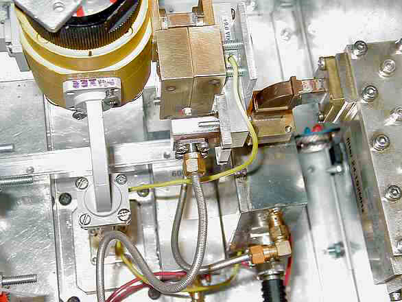
Heatsinking: The PA was mounted in place at the transmit port of a substantial waveguide switch. In addition, it was placed in a "sandwich" heatsink comprising two 25mm thick brass blocks and a 3mm thick aluminium plate (see upper middle section of the photograph above).
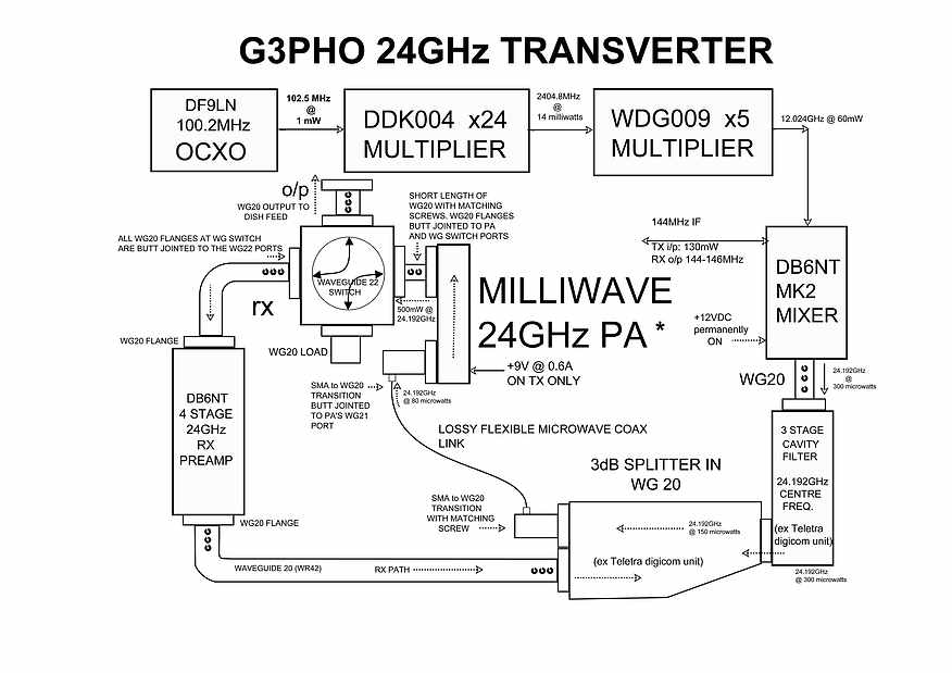
Interfacing to existing equipment: The existing 24GHz transverter at G3PHO consisted of an IC202S 144MHz prime mover driving a waveguide system using a DB6NT Mk2 mixer which in turn fed a DB6NT 4 stage RF amplifier (reversed on receive to act as an LNA) to give 65 to 70 milliwatts output. The DB6NT mixer is driven by a Local Oscillator chain, at 24.048GHz, consisting of a DF9LN OCXO at 100.2MHz driving a G4DDK004 multiplier to 2.4GHz and then multiplied by a G3WDG009 x5 multiplier to 12.024GHz to feed the DB6NT Mk 2 subharmonic mixer. Extensive use of waveguide WG20 (WR42), with matching screws and butt jointed to the WG22 (WR28) waveguide switch, produced a low-loss transfer to the antenna feed horn (see diagram below). The introduction of a THIRD size of waveguide, WG21 (WR34) in the form of the Milliwave amplifier input and output ports caused some consternation at first (!) but experiments at butt jointing waveguide 20 flanges directly to these ports showed that losses, if any, were minimal and a good match could be achieved by the liberal use of matching screws in the WG20 sections.
This photograph above shows the Milliwave amplifer in the top of the picture (yellow lead going to it) and sandwiched between the two-section brass block and the aluminium plate. Note the short section of WG20 joining the output port of the Milliwave amplifier to the waveguide switch. Note the WG20/sma transition bolted to the input port of the PA. This transition is a commercial, low insertion loss, 24GHz item.
The following diagram shows the present transverter system in detail.
Results so far
The addition of the Milliwave module to my system has provided a number of interesting two-way contacts with other 24GHz operators over the period April to June 2001. There is no doubt that the 500 milliwatts at the feedhorn of the 35cm offset dish antenna has made a considerable difference to the signal levels and paths achievable, when compared with the 65 milliwatts of the earlier transverter.
One very obvious feature is the strength and number of reflections that can be made on the 24GHz band with higher power. The smallest object seems to reflect much better than several watts of 10GHz could produce! In tests with G0HNW over short range (25-50km) paths between his home station and my portable 24GHz station, full two-way contacts have resulted after both of us have beamed at a common reflector, the Holme Moss TV transmitter mast. In one test, G3PHO/P aimed his 24GHz dish at a 100 foot tower a few yards south of his /P location. The reflected signal then travelled 25km to the northwest to strike the Holme Moss TV mast and was then, in turn, reflected east some 6km to G0HNW at home. Signal levels were S9 both ways! Paul,G0HNW, uses a very similar system to G3PHO but claims 720 milliwatts out of his Milliwave PA as against the measured 500mW of G3PHO's system.
More tests with Paul have been carried out
from various hill top locations in the Peak District National Park back
to his home location. In June 2001, G3PHO/P worked him on the direct path
between IO93AD and his home in IO93CN, almost 50km. That's not a big distance
until you examine the terrain profile (see below) between the two stations!
The straight line shows the first obstruction between G3PHO/P and G0HNW.
The terrain profile is obviously very challenging for a 24GHz signal! Reports
of RS53 on SSB were exchanged both ways.
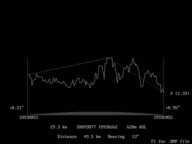
TERRAIN PROFILE BETWEEN G3PHO/P LOCATED AT MERRYTON LOW TRIANGLE (IO93AD51) AND G0HNW (IO93CN) AT HIS HOME STATION IN HOLMFIRTH, WEST YORKSHIRE
The first obstruction is 29.3km from G3PHO/P ... after that the profile looks like the Himalayas!
On one occasion signals were heard between the two stations via rainscatter. The higher power of the Milliwave PAs makes this a real possibility when the weather conditions are suitable. Some years ago G3WDG worked G3LQR on 24GHz via snowflake scatter!
Other operators have adapted their 24GHz transverters to take the Milliwave PA. You can read about them by following this link:
OTHER SYSTEMS USING THE MILLIWAVE PAIf you have successfully incorporated a Milliwave PA into your system I would be most interested to receive details for publication on this website and maybe into a downloadable PDF booklet. Please contact me, Peter Day, G3PHO by email.