(examples submitted by other microwavers)
This section describes various approaches to using the MilliWave 24GHz PA. Many thanks to all who have contributed information. More is welcome. Please email your notes directly to the webmaster.
FROM HAROLD GROVES, G3UYM
I have completed the rebuild of my 24GHz rig to include the Milliwave PA and a coax version of the DB6NT MK3 transverter.The line up is now G4DDK oscillator --> G3WDG x 5 multiplier --> DB6NT MK3 transverter -->gold filter --> circulator(both ex DMC "grey cube")--> DB6NT Rx pre-amp, Milliwave PA and WG switch.Two WG/SMA transitions were used, one at the input to the PA the other at the Rx pre-amp.The input and output ports of the PA module were butt joined to WG20 and heat sinking provided by a copper block fixed to the module and chassis.The PA produced 630mW for 80uW imput. This was measured for me by Bryan G8DKK.
Harold, G3UYM
FROM
PAUL LONGSTAFF, G6UAJ
This is my system solution without the use of a 24GHz transfer relay (as I do not have one!!). The waveguide switch is manual and is only needed if a single dish is being used. The system is waveguide up to the 24GHz mixers. I have achieved about 39dB gain and the specified 600mW (+/-1dB) from the Milliwave PA, without fabricating any waveguide converters (ie WG20 coupled to the Amp, using just 2 mounting screws on each flange.) I found only a very small increase in power was available by tuning the waveguide before and after the Amp. I have used an 18GHz power meter with an estimated frig factor for 24GHz. My measurements should be within 1dB or so.
FROM CHRIS TOWNS, G8BKE
I achieved just over 400mW output from my PA with 0.2mW input. 100mW of this was achieved by the addition of 10BA tuning screws in the WG 20 at the input and output of the PA (see Web site www.qsl.net/g8bke/index.html ) for detailed pics. More output may be possible if the output of the transverter can be increased, but for now I'll live with 6dB more than I had before!
AN INTERESTING IDEA FROM JOHN ANDERSON, WD4MUO
This item was originally posted on the WA1MBA and San Bernardino Microwave Society Reflectors, wh0 we gratefully acknowledge.
From: owner-sbms@altadena.net on behalf of John Anderson
[wd4muo@webaccess.net]
Sent: 11 January 2001
To: microwave@wa1mba.org; sbms@ham-radio.com
Cc: W0EOM@aol.com
Subject: W0EOM 24 GHz Power Amp Connections
A tapered transition from WR-42 to WR-34 is quite easy to make since
the height of both waveguides (or at least the dimensions given for W0EOMs
amplifier ports) is the same (0.170 inches). Using a jewelers saw, slit
a 2.5 inch or so piece of WR-42 waveguide down the center of both
broad walls for about 2 inches (ideally the taper should have a length
greater
than 3 guide wavelengths). Squeeze the sides together and measure
the interior dimension of the open end. If it is greater than 0.340" recut
the narrowed slit with the saw (be careful, this is a blade breaker) or
run a piece of sandpaper through the slit several times. Repeat this squeeze
and recut operation until the interior dimension is 0.340". Debur the slits,
bind the open end together with iron wire and silver solder the slits.
(If the slits are in the exact center of the broad walls you can probably
soft solder them or possibly not even solder at all).
The amplifier hole pattern is not that of any standard flange of which I am aware. Special flanges to fit the pattern can be made from 0.100" - 0.125" thick brass stock. Of course the WR-42 end of the transition would take a standard flange.
I think that one correspondent is correct in believing that the
port side of the amplifier is the heat sinking surface. I would take one
of the heat sinks that has a channel down the center of the fins, i.e.
H-H-H----H-H-H, or LLL___LLL, and drill and file 0.340" x 0.170" holes
through the mounting surface of the heat sink in the proper positions
and drill the appropriate mounting holes. Then use long bolts to pass through
the transitions custom flange, through the heat sink and into (through?)
the amplifier mounting holes.
For those interested in making adapters or transitions for other waveguide sizes I wrote a paper on this subject for the 1998 Microwave Update Proceedings. It includes waveguide and flange data for WR-42 to WR-03 (but not WR-34) reprinted from the Aerowave, Inc. catalogue.
73, John WD4MUO/0
FROM MARTIN FARMER, G7MRF ~ A "DELUXE" HEATSINKING IDEA!
Martin always makes a good job of the metalwork when he buiolds his microwave equipment. The heatsking arrangements he has done for his Miliwave PA are a good example. Just look at the following photos. What a beautiful job he has made!
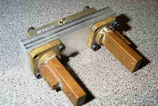
The photo above shows how he has made two sma/WG20 transitions to
suit the Milliwave PA. The sma sockets are not yet mounted in this photo.
Notice the provision for matching screws here. The block of aluminium between
the transitions and the PA module serves both as a WG20-WG21 (WR42 to WR34)
transition and as a partial heatsink. The following photograph illustrates
the idea:

This complete assembly is drilled for mounting to a larger heatsink .... see photo below:
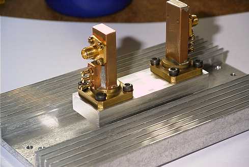
Here you can see the finished heatsink assembly with the sma sockets
and matching screws also installed. The large, finned heatsink is
drilled to enable easy mounting into the equipment case.
![]() RETURN TO PREVIOUS MILLIWAVE PAGE
RETURN TO PREVIOUS MILLIWAVE PAGE