SETTING UP YOUR GUNN TRANSCEIVER
Once the boards have been assembled, it is suggested you connect all parts
of the system together in the manner of the breadboard shown in the previous
page. If you are using the Gunn supply voltage to adjust frequency, you will
find that optimum speech quality occurs over a limited range. Ideally you
should arrange to have TWO Gunn systems (your friend's and your own) on the
bench at the same time so that both can be made compatible with each other.
You should then set the coarse frequency adjustment using the adjusting screw
already fitted to each doppler module, with the Gunn volts set at mid-range.
This will give you a small, but effective variable tuning range.
Initial checks:
-
Do not connect the supply lead to the Gunn diode terminal just yet...
-
Check each module in the system separately, leaving the final connection
of supplies to the Gunn diode until last.
-
Check that you have +12 volts dc applied to the transceiver and check that
each module has the correct voltages (refer to the circuit diagrams).
-
Check that the Gunn power supply is giving some 6 to 8 volts dc at the output
of pin 2 of the LM317T regulator and that adjusting the 10 turn potentiometer
actually varies this output. The psu should not exceed about 9.5V out or
go below 5.5V out. Some substitution of components in the psu (especially
the 1K and 240 ohm resistors) may help to achieve these limits.
-
If you have an oscilloscope (and know how to use it!) check the Gunn volt
supply for transients and "noise". Make sure you have by-passed both pins
2 and 3 of the LM317T regulator IC with 1uF tantalums, soldered right up
at the regulator itself. More bypassing may be needed if there are "spikes"
on the output.
-
Check that the transient suppressor network is fitted across the gunn diode
terminal on the doppler module.
-
Connect a 1 or 5 mA meter from the mixer diode terminal to ground as shown
in the diagram on the previous page.
-
When all voltages on all boards are found to be correct, then make the final
connection of the PSU to the Gunn diode terminal on the doppler module and
SWITCH ON!
The milliameter should now give some indication of the mixer diode current.
Don't worry about the amount at this stage, although you can adjust the matching
screw near the mixer diode for around 0.5 to 1mA if you wish.
The loudspeaker should by now be giving a healthy hiss!
-
Find a suitable 30MHz signal source (eg an fm modulated signal generator)
and tune the core in L on the TDA7000 board until you hear the signal. The
board is basically "no tune" apart from that adjustment!
-
Set the diode current to 0.5mA by adjusting the appropriate screw (see the
diagram on the Solfan module). Much more than this (certainly 1mA or
more) will be detrimental to the receiver noise figure. Too little (ie below
0.25mA) will have the same effect.
-
If you have a preamplifier stage between the diode mixer and the input to
the TDA7000 receiver then peak that up for maximum received signal. This
is best done with the weakest possible signal input at 10GHz.
Next, you have to find the 10GHz amateur band!
One of the simplest ways to do this is to use a 2m, 70cm or 23cm low power
signal to drive a microwave diode so that a whole string of harmonics is
produced, at least one falling into the 10GHz band. The higher the original
signal the more likely you are to find the correct harmonic. Only a few
hundred milliwatts drive (say up to 500mW) will be needed to produce
a few, easily-heard microwatts on 10GHz. The easiest way to do this is to
simply connect a microwave mixer diode (eg a 1N23 or similar, or even a more
modern type such as one taken from a surplus X band Satellite LNB) across
a BNC socket. Solder it from the spiggot to the body of the connector. Then
feed 2m, 70cm etc in via a length of coax. Poke the diode end of the assembly
near to the mouth of the doppler module's waveguide and coarse tune
the module until you hear the signal. This is made much easier if you switch
on the TONE OSCILLATOR which is part of the simple circuitry described in
this article.
The following table shows some useful harmonic
relationships:
|
Input Frequency
|
Multiplication Factor
|
Output Frequency
|
|
144.000MHz
|
x71
|
10.224GHz
|
|
144.000MHz
|
x72
|
10.368GHz
|
|
432.000MHz
|
x24
|
10.368GHz
|
|
1296.000MHz
|
x8
|
10.368GHz
|
Using a 144MHz drive source can lead to some errors, since more than one
harmonic will fall within the 10GHz amateur band. Hence it is recommended
that you use 432MHz or 1296MHz source.
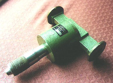 You might have access to an accurate frequency counter..use
it! You may also be able to obtain an X Band wavemeter at hamfests or radio
rallies. The one pictured here was bought for only £10 UK (about $16
US) and was indispensible to writer in his "early days". This type of wavemeter,
with waveguide ports is easy to use. Tuning the micrometer dial will cause
a "suck out" or dip in mixer diode current when the frequency of the
Gunn coincides with that of the micrometer cavity. Ideally you should have
a microwave detector diode mounted in a waveguide cavity and place this after
the wavemeter. In other words, the wavemeter should be put between the Gunn
oscillator and the diode receiver. Sometimes the flanges may not match the
ones on your Gunn transceiver. You will then need a short length (say 6cm)
of waveguide with a round flange at one end and a rectangular one at
the other for use as an adapter.
You might have access to an accurate frequency counter..use
it! You may also be able to obtain an X Band wavemeter at hamfests or radio
rallies. The one pictured here was bought for only £10 UK (about $16
US) and was indispensible to writer in his "early days". This type of wavemeter,
with waveguide ports is easy to use. Tuning the micrometer dial will cause
a "suck out" or dip in mixer diode current when the frequency of the
Gunn coincides with that of the micrometer cavity. Ideally you should have
a microwave detector diode mounted in a waveguide cavity and place this after
the wavemeter. In other words, the wavemeter should be put between the Gunn
oscillator and the diode receiver. Sometimes the flanges may not match the
ones on your Gunn transceiver. You will then need a short length (say 6cm)
of waveguide with a round flange at one end and a rectangular one at
the other for use as an adapter.
Note that the frequency 10.368GHz is also the narrowband operating frequency.
If you have a narrowbander near to you, he might put out a CW signal for
you to listen for and use as a calibration point. You may be fortunate enough
to have a 10GHz beacon near to you. By taking your wideband gear out to an
easy line-of-sight path between you and the beacon you should be able to
find it and establish another calibration point.
A full list of European and UK microwave beacons
is available within these webpages.
This simple equipment is broadband and relatively unstable so a calibration
point of 10.368GHz and one of say 10.365GHz will not show up as being very
different on your tuning dial. However you should try to get a wide range
of calibration points so that your Gunn Volts ten-turn potentiometer can
be fitted with a vernier dial. A calibration chart can then be drawn.
If you are aligning two or more Gunn tranceivers, it is wise to set
them up so that they can hear each other. Set up one first and then
adjust the coarse frequency screw on the other, with the Gunn volts set at
mid way, until you hear the tone from the first set. If and only if, the
Intermediate Frequencies of each transceiver are identical (eg 30MHz) you
will hear each transceiver in the other simultaneously..... in otherwords
you will have duplex operation like a telephone! Using the tone oscillators
will give an unmistakable beat note! In this situation the Gunn oscillator
one of transceiver will be + or - 30MHz from the other transceiver, thus
producing an IF of 30MHz. You cannot operate duplex if the receiver IFs are
not the same.
Once the frequency range is established you should repeak each adjustable
component in the transceiver to optimise the equipment around the 10.3 to
10.4GHz section of the amateur band.
OPERATING UNDER PORTABLE
CONDITIONS
It is common practice to have a VHF radio at each end of the proposed microwave
path. 144MHz or 432MHz, ssb or FM, are commonly used in Europe and the USA
This VHF link is the "talkback" and it is on this that both parties discuss
microwave frequencies, bearings and confirm that the microwave signal
is being heard. Of course you can use any talkback frequency you like but
in the UK we use 144.175MHz ssb, moving off that spot frequency once talkback
has been established.
When trying to establish contact under portable conditions I suggest one
transceiver is set to a fixed frequency (say mid travel on the Gunn volts
tuning control) and the transceiver at the other end is used to tune around
until the tone is heard.
Once on site you will need to establish an accurate heading for your antenna.
Horns are easier to point than dishes! For your first contact, over a few
metres or so, anything will work but once you put dozens of kilometres between
you and your pal you will need to point your antenna accurately. Obviously
you must use a good compass to establish the direction. The bearing should
be worked out in advance either by using maps or one of the excellent computer
programs available. This website has just such software
available for download. It was written by Andy Talbot, G4JNT, and
is widely used in the UK and Western Europe. G4JNT Contest Suite includes
a contest logging and scoring program, distance bearing calculations and
much more.
Always work in degrees TRUE, not magnetic. Bearings derived from a
map will be near enough to True Bearings. Of course when using your compass
you will need to add (or subtract depending on which part of the world you
live in) . In the UK the magnetic variation is around + 5 degrees in the
UK at the present time (1998). However this varies around the country. Your
map should have the figure printed somewhere in the margin.
The photograph on the right
shows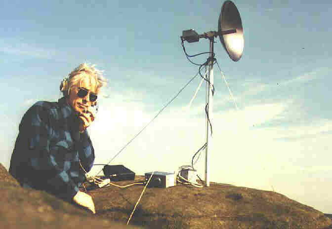 G3PHO/P, in the summer of 1985, working
over a 160km path on 10GHz wideband. The Gunn transceiver is split into two
separate units.... on the short mast is the Gunn oscillator and diode mixer
"head", feeding a small 20 inch diameter dish. On the rock below you
can see the power supply/modulator/tone oscillator and 30MHz receiver
unit. The modulated Gunn voltage is fed up to the microwave head via a short
cable while a length of 50 ohm coaxial line brings the 30MHz IF signal back
to the unit below. A 30MHz preamplifier is fitted into the head unit to provide
a good match and sufficient signal to the IF unit below. The measured Noise
Figure of this system was around 8dB, quite good for a diode mixer!
(Modern, narrowband 10GHz equipment is now commonly found with Noise Figures
around 1 to 2dB). To the immediate right of G3PHO is an IC202S ssb/cw handheld
transceiver for 144MHz. This was used to established talkback. The 3 watts
p.e.p and quarter wave whip antenna of the IC202S was generally adequate
over line of sight paths such as these.
G3PHO/P, in the summer of 1985, working
over a 160km path on 10GHz wideband. The Gunn transceiver is split into two
separate units.... on the short mast is the Gunn oscillator and diode mixer
"head", feeding a small 20 inch diameter dish. On the rock below you
can see the power supply/modulator/tone oscillator and 30MHz receiver
unit. The modulated Gunn voltage is fed up to the microwave head via a short
cable while a length of 50 ohm coaxial line brings the 30MHz IF signal back
to the unit below. A 30MHz preamplifier is fitted into the head unit to provide
a good match and sufficient signal to the IF unit below. The measured Noise
Figure of this system was around 8dB, quite good for a diode mixer!
(Modern, narrowband 10GHz equipment is now commonly found with Noise Figures
around 1 to 2dB). To the immediate right of G3PHO is an IC202S ssb/cw handheld
transceiver for 144MHz. This was used to established talkback. The 3 watts
p.e.p and quarter wave whip antenna of the IC202S was generally adequate
over line of sight paths such as these.
This type of simple microwave and talkback gear was easy to carry up to the
top of Britain's highest mountains. As narrowband has taken over from wideband
as the preferred mode of operation in Europe and the UK, higher and higher
power levels plus bigger and bigger antennas have become the norm for the
144MHz talkback. G3PHO/P now has to use nearly 100 watts p.e.p to an 8 element
DL6WU design yagi. The 5 amp dryfit, gel battery has given way to a
couple of 80 amperehour lead acid types...hardly backpack portable any more!
If you build the simple wideband gear of the "old days" you can really enjoy
yourself in the Great Outdoors..provided you have a like-minded friend or
group of friends.
Your antenna must also, initially at least, be accurately levelled. A small
bubble level on top of the equipment is all that is required. If you use
a tripod to mount your 10GHz gear it may already have such a level built
in.
Provided you have set your antenna direction accurately and are confident
that each transceiver is compatible in terms of frequency range, there is
no reason why you should not have almost immediate results over a short,
line-of-sight path (say 10km). Once you have had a few contacts of this kind
you can then embark on increasing the distance..... who knows, you might
eventually have the thrill of breaking the 100km, then the 200km
"barriers"..or even more!
The rest is now up to you! You have a fascinating time ahead....
trying out bigger and better antennas, new paths, better receivers and so
on. Above all, you will have joined that happy group of amateurs who build
their own equipment and who are always ready and willing to share their
enthusiasm and expertise with others. The thrill you will get when you make
your first 10GHz QSO is like nothing else on earth!
WELCOME TO THE WORLD ABOVE 1000MHz!
 RETURN TO FRONT PAGE