Towards the back end of year 2000 I bought a 10GHz
transverter kit from Michael Kuhne, DB6NT
. As with my earlier 5.7GHz DB6NT
kit I found construction very straightforward and the equipment was made
and aligned in two or three days. It was then "soak tested" for a couple
of months ... i.e., left in the receive position on a shelf just above
the home station gear. This allowed the crystal oscillator and other components
to age and thus hopefully increase reliablity and stability once the unit
was put into service.
Up to this period I had been
using a 5 watt transverter based on a modified Microwave Associates Rapac
unit (the so called "Whitebox"). I have
ten years of good service from this equipment but, over the years I have
added varioous other modules to the basic "whitebox" and the equipment
had become both heavy to handle and a virtual "rat's nest" inside! The
new DB6NT transverter was obviously the way to go as it is a self-contained
250mW output transverter with a noise figure approaching 1dB.
For the new transverter I decided
to house the DB6NT module in a surplus mobile radio case (ex Pye Cambridge
for those of you in the UK!), A complete Cambridge was purchased at a radio
fleamarket for only £2 ($3 US). I stripped out all of the old VHF
FM transceiver from the case and drilled it to take the new microwave modules.
Fortunately I was able to use many of the holes left vacant in the original
Cambridge. Once the box was resprayed with a silver "hammer finish" paint
it look really good. A baseplate of 3mm thick aluminium provided a firm
base for the various modules.
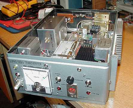
This photo shows the almost completed transverter.
From this it is obvious that the DB6NT transverter module has been joined
by several others! I had decided to make the whole thing a self-contained
5 Watt output equipment that has high frequency stability and resettability.

This photo on the right shows the various modules
in the finished transverter. Top left is the IF interface unit. This contains
a couple of cheap bipolar transistors and a small 12V relay. An IC202S
144MHz transceiver, whose power output has been reduced to 130 milliwatts,
is fed in via a BNC connector on the front panel. A short coax link takes
this to the interface unit where, on pressing the PTT switch on the IC202S's
microphone, the two transistors key the relay which in turn grounds the
PTT connection on the DB6NT transverter module. The transistors are activated
by the 4.5V that appears on the IC202 coaxial line during receive. When
that voltage is removed on TX the relay goes over.
The aluminium box in the top
right corner of the box is a 106.5MHz Oven Controlled Xtal Oscillator.
This is to a design by John Hazell,
G8ACE. John has spent much of the past two years developing highly
stable oscillators and this one is a little beauty! Approximately 1 milliwatt
of 106.5MHz is taken to the DB6NT transverter by the rather thick coax
line you can see in the top of the photo. Of course you can use the internal
xtal local oscillator if you like but I found that is drifted slightly
between transmit and receive once I had fitted the 5 Watt PA. I assume
this was due to thermal effects. The outboard G8ACE OCXO is kept at 60
degrees Celcius and seems immune to external influences. hence the stability
is much better. I arranged for the G8ACE LO to have a separate 12 volt
supply so that it can be switched on when the rest of the transverter is
off. This allows me to leave it on in the radio shack for weeks at a time,
ensuring excellent stability and readiness for immediate portable operation
when needed.
Centre left in the photo is
the DB6NT transverter module itself. The receive input is taken directly
from the Dynatech microwave coaxial antenna change-over relay while the
TX output drives a surplus Qualcom 1 watt PA via a 20dB attenuator. The
RF output control inside the DB6NT unit is then adjusted so that a few
hundred microwatts appears at the input of the Qualcom. The Qualcom PA
produces some 800mW to drive a DB6NT 5W PA. I chose such a low gain final
stage so that if it ever broke down I would still be above to run a the
1 watt output level by merely juggling around with the semi rigid coaxial
links! Hope fully the 5W PA will never break down but you never know!
The Qualcom PA is a surplus
14GHz unit availavble a few years ago in large quantities and at a very
reasonable price from
Chuck, WB6IGP
of the San Diego Microwave group. With careful pruning of the microstripline
circuitry it can be persuaded to give a watt or so at 10GHz for a mere
"whiff" of drive at the input. Naturally it requires good heatsinking and
a small power supply giving 10V at around 1 amp and -5V negative
bias at a few milliamps. The photo shows the Qualcom amplifier fixed to
a substantial finned, black heatsink. The PSU is housed in the small diecast
aluminium box fixed to the lower wall of the transverter case.
The DB6NT 5 Watt PA can be
seen in the lower right hand corner of the photograph. This is self contained
and requires only a switched 12V supply.
The diecast box with two large
electrolytic capacitors in the top is a 28VDC supply for the coaxial relay.
The electrolytics are low ESR types and were found essential to remove
"noise" produced on both input and output lines is this PSU since
the supply is a switch mode type. If this noise were allowed to get onto
the 12V LO feed there would be some very undesirable modulation/spurious
effects!
The brass enclosure clamped
to the lower right wall of the equipment is a sequencer module that changes
the supply voltages and coaxial antenna relay over in a controlled sequence
so that the receiver front end devices are not destroyed by having
5 watts pumped into them before the relay has gone to transmit! I have
found it wise to use a sequencer with power levels of 1 watt and above.
Yes, there are operators who seem to get away with no sequencer at all
but I don't take chances!
On the centre of the right
wall of the box can be seen the WG16 waveguide to sma transition. This
is a simple homemade affair and has provision for three matching screws.
Of the two screws shown in the photo only one has the effect of increasing
the power output, indicating a reasonable match to start with.
You can see two small pcbs
with relays in the photo (lower left and top right in the second photo).
These key the 12V supplies to the various modules and are controlled by
the "12V dc output on TX" provided by the DB6NT module and further controlled
by the sequencer. I found this better than putting the various voltages
through the sequencer directly as the latter only has to switch the low
current relays instead of the higher currents drawn by the amplifiers.
Several of the modules are
protected by their own individual fuses. It is essential to put a fuse
in the "12V DC out on TX" line from the DB6NT module, as I learned to my
cost when I accidently grounded its feedthrough connector. The result was
to destroy a power FET in the DB6NT's internal switching circuit!
This equipment is now the main
10GHz equipment as used in my "MICROWAVE
STATION FOR THE YEAR 2000"
described elsewhere in these pages.