Back in the early 1970s, when I took up 10GHz in real earnest, almost all UK 10GHz work was done by portable stations. The equipment was lightweight, wideband FM, gunn diode gear. I combined my two main interests, amateur microwaves and mountaineering, so that my radio gear was sufficiently small and light weight to be carried in a rucksack, along with food and protective clothing, first aid kit, etc, up the highest mountains of the UK. Tripods were too cumbersome and my early gear was mounted on a short, guyed mast, with 144MHz talkback being restricted to 3 watts o/p from and IC202S and its whip antenna! Since the wideband FM paths were almost all line-of-sight, even at 245km, this low power VHF transceiver worked very well indeed.
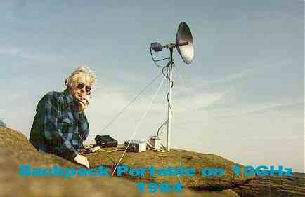
This photo shows me back in 1984, portable at Bleaklow in North
Derbyshire, approximately 2060 feet above sea level, on a wide, desolate
stretch of heather moorland ...an hour's walk from the car and not a tree
in sight! The 10mW Gunnplexer and PW 18 inch dish with "penny feed" worked
some excellent DX for the wideband mode, including the longest LOS path
available in the UK (Cairnsmore of Carsphairn,
S. Scotland to Mt. Snowdon in North Wales). "Backpack portable",
as I call this, offered both valuable exercise of the body and a good day
out with the radio!
As the years went by, the equipment grew bigger and heavier for
we had reached the days of narrowband modes! The early narrowband gear
was very low power (350 microwatts output!) but since it was of all waveguide
construction it was not as backpackable as the wideband gear. In addition
it tied up the IC202S 2m rig as a transverter "prime-mover" so an additional
144MHz ssb transceiver was needed for talkback on 2m. Since narrowband
allowed non LOS contacts to be made, the 2m talkback signal was often
very weak using the internal whip antenna on the transceiver and
so yagi beams were employed. All this led to operation from a vehicle,
parked by a road side or track and no long on mountain peaks! Gone were
the days of small Yuasu dryfit batteries! In their place were heavy
duty car batteries (too heavy and dangerous to be backpacked up hills).
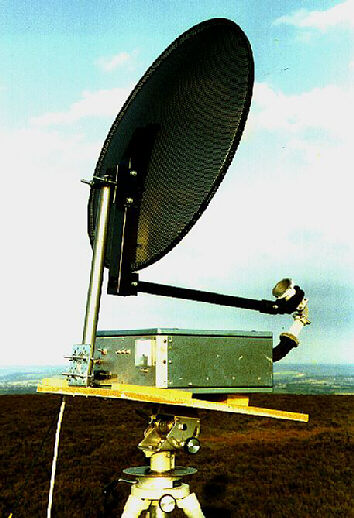
This next photo shows the 10GHz ssb gear used by me in the early to mid 1990s. It includes a 10GHz to 144MHz transverter housed in a surplus, weatherproof case made by Pye and mounted on a sturdy tripod. The case formerly housed a VHF FM transceiver, the "Vanguard". The 144MHz prime-mover is an Icom IC202S ssb/cw transceiver with power output reduced to 100 milliwatts for the 10GHz unit input, to which it is connected via 15 feet of coaxial cable. The 144MHz signal is then upconverted to ssb or CW on 10.368 to 10.370GHz. The single coaxial line to the 10GHz unit carries a control voltage for send/receive, as well as RF input and output. The transverter shown here is still the primary equipment today, in 2000AD, though there have been recent modifications to increase the power output to 5 watts and the receive noise figure to around 1.5dB or so (see below).
The 60cm (2 foot) diameter dish antenna shown here was used in the mid 1990s and is a surplus Satellite TV 60cm offset-fed type. The horn feed shown in this photo is also ex-SatTV but I replaced it with a homebrew dual-mode horn made from copper pipe plumbing parts. This horn feed is described elsewhere in these webpages.
Up to the end of 1999 the output was some 900 milliwatts. The tripod shown in the above photo is ex-TV studio by National. The calibrated compass dial is essential for accurate headings as the dish beamwidth is quite sharp, in the order of 3 degrees or so. It is also very sharp in the elevation plane so an adjustment is provided for this. At times, during certain propagation conditions such as "rainscatter", the dish needs to be tilted upwards by several degrees.
The whole portable assembly shown above could be installed in a matter of a few minutes. During rainy weather, a large, transparent plastic sheet can be dropped over it for protection.
The equipment is powered by a 12 volt 85 ampere hour, sealed, lead-acid battery. This provides a weekend's normal operation.
All operation was, and still is, from a VW Campervan ..... a far cry from the windswept mountain tops of yesteryear. Warmer and safer it might be but I still yearn for the summits and the challenge that backpacking brings!
Recent changes:
In 1997 I changed the antenna to a 1.2m diameter prime focus dish. This uses a scalar ring horn, the "Chaparall" feed, which came with the dish. Although commercially used on 11GHz, the feedhorn is still an excellent match on 10.3GHz.
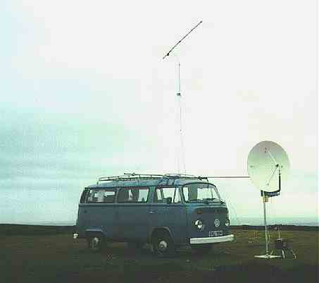
This photograph shows the whole portable station including the VW van, roof-rack mounted antenna scaffolding and 144MHz mast and 8 element yagi (this being homemade to the excellent DL6WU design) as used up to the end of 1999.
The 144MHz talkback station runs an 80 watts PA driven by an old but trusty TS700A, much modified to provide a better receiver front end and completely rebuilt power supply.
The mast and dish support are very heavy duty, made of 5mm wall
thickness, 50mm diameter, aluminium pipe. Excellent pipe clamps, made by
Kee Klamps, are used to fasten the mast to its horizontal support
and baseplate. The next photos show these in detail.
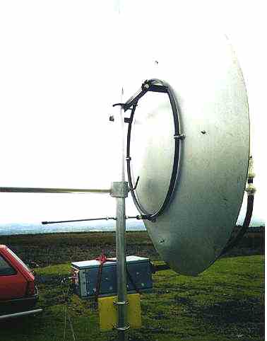
The Kee Klamp making the rotary T-join at the rear of the dish, between
the two dish mounting points, is mounted on the vertical mast while
the latter is being assembled on the ground. The mast and dish are then
raised into the vertical position so that the clamp slides over the horizontal
support. It's quite a job in strong winds though! The dish is secured in
the desired heading by tightening the allen screw set in the clamp (an
allen key can clearly be seen in the photo). The disadvantage of the system
shown here (in use to the end of 1999) is that the dish cannot be rotated
a full 360 degrees since the horizontal support gets in the way. This was
not been much of a problem when operating from the North of England as
almost all activity is in a broad arc from SE throught south to south west.
So, if the VW Camper was aligned North/South, the dish could cover the
arc quite comfortably.
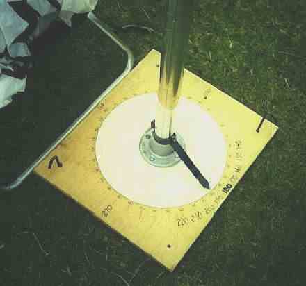
The base of the dish mast is set in another Kee Klamp mounted on a wooded
baseboard upon which a calibrated 360 degree compass scale has been
drawn and then clear varnished to weather proof it. The photograph below
shows this. Note the tent pegs holding the base board steady while the
mast is rotated. The large pointer is adjusted to give the correct true
compass reading on a local landmark or microwave beacon. Once done it is
then a very simple matter to point the dish in any direction with an accuracy
of +/- one degree. To enable rapid beam headings I carry
a list of over 300 headings to well known microwave portable sites
and home stations. This is usually enough to cope with a full day's microwave
contest activity. Site bearings not on the list are measured from a map
although some home and portable stations now carry programmable calculators
or laptop computers to work out distance bearing calculations.
Today, the 10GHz transverter has a total system
noise figure (at the antenna flange) of around 1.5dB, the result of a homebrew
HEMT receive preamp installed a couple of years ago ahead of the existing
2 stage GaAsFET module. The transmit output is now a "healthy" 5 watts
as I have recently added a DB6NT 5 watt PA block to the system.
In March 2000 I changed vehicle and acquired a newish VW diesel Transporter.
Details of the new portable
microwave system I have set
up with this vehicle can be seen by following the link shown below.
I hope to be able to operate /P for a good many years to come!