| A
DB6NT Mk2 mixer has been in use for several years but only in "barefoot"
operation (ie with no PA or receive preamp). This fed a 35cm offset fed
dish, tripod mounted, alongside a low power Gunn TX/RX for wideband FM.
While the barefoot mixer could work over fairly long distances (ie 100km
or more) it suffered from low RF output (only 300 microwatts!) and
a poor noise figure (8dB).
Over the winter of 1999-2000 I upgraded the 24GHz narrowband gear by installing a DB6NT four stage preamp/PA stage. This excellent design by Michael, DB6NT, provides some 95 milliwatts output (without filters and change-over, etc.) and a noise figure around 2dB. To use it on both transmit and receive, I built it into a waveguide switch operated system and in a new, homemade, aluminium box. The following photos show the equipment in detail: |
G3PHO
24GHz NARROWBAND EQUIPMENT |
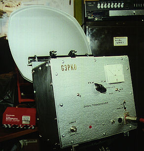
PHOTO 1: Front panel controls and connectors RX/TX switch, Local Oscillator DC on/off, main Transverter DC on/off, Meter readout Battery +DC volts or RF milliwatts out, 144MHz IF in/out (BNC), +12V DC in. The whole system is fused at 1.6A. A red LED indicates when the LO is operating, while a green LED indicates power is on to the main transverter.
|
The box is rather large (27cm x 24cm x 20cm) as it has to house a waveguide switch and waveguide loop. The 35cm offset-fed dish is fixed to the front of the box but swivels on a short, horizontal 24mm diameter tube. This allows the flexiguide feed to be detached from the dish feedhorn and the dish swung out of the way for the equipment to be connected to test gear. The RF in/out flange is in Waveguide 20 (WR42) and is connected to the rectangular feed horn via a short length of rigid WG20 plus a length of flexible WG20. Matching screws are installed at the feedhorn to enable a low VSWR at that point.
|
| The main unit contains the waveguide and module assembly. Most of the waveguide is WG20 (WR42) but the four port waveguide switched, which is used to turn the DB6NT amplifier around from receive to transmit, is in WG22 (WR28). I was lucky enough to purchase two of these WG switches for the "princely" sum of £10 (about $15 US)and decided they could be used at 24GHz quite successfully. I cannot measure any appreciable insertion loss as a result of using this odd waveguide! WG22 (WR28) is more easily found on the surplus market than WG20 and is therefore highly recommended for this band! Unfortunately WG20 flanges will not mate with WG22 ones. This was only needed at the ports of the WG switch so I merely filed out 2 diagonally-opposite holes in each of four WG20 flanges so that I could fix them to the WG switch. I was lucky enough to have a number of E and H plane 90 degree bends in WG20, complete with flanges. These allowed me to make up a waveguide loop around the switch, as can be seen in photo 3. The straight sections of WG were made up to fit accurately between the bands. Three matching brass screws were placed in each section, near to the bends. In practise, only one matching screw in each section has any effect and even then it does not penetrate very far into the waveguide. All this indicates a reasonable match to begin with. |
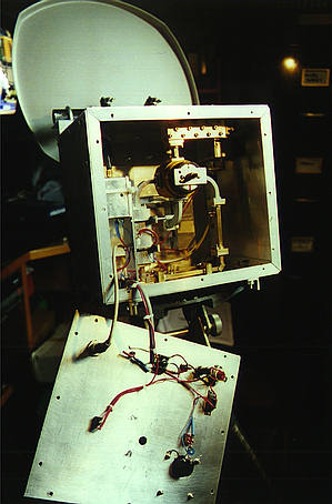
PHOTO 2: behind the front panel The front panel is easily removed and is self-contained, in that all the front panel connectors, meter and LEDs are wired so that they plug into a common connector, fixed to the floor of the aluminium box. Thus the transverter can be operated with the lid in the position shown here, or the lid can be removed for wiring modifications without disturbing the interior of the unit. |
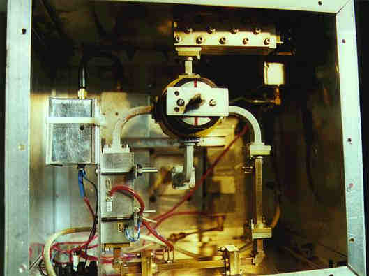
PHOTO 3: Showing the various modules inside the unit. |
The
various modules in this equipment are as follows (refer to photo 3 opposite):
Far left foreground: DF9LN 100.2MHz Local oscillator (output 1mW) Next left foreground: DB6NT four stage HEMT preamp/PA (output 95mW) Rear left: G4DDK004 multiplier to 2.4048GHz (output 15mW) Upper centre foreground: Four port WG22 waveguide switch Top centre foreground: Multi-cavity image filter (ex Teletra 23GHz unit) Rear
right background: G3WDG009 x 5 multiplier (2.4048
to 12.024GHz) Right
wall: DB6NT Mark 2 subharmonic mixer |
CIRCUIT DETAILS: The DF9LN oven-controlled crystal oscillator is accurately maintained at 100.2000MHz such that the final frequency output at 24GHz is within 1kHz of nominal. The DF9LN is kept running permanently both in the shack and when out portable. It is never switched off! This can be conveniently achieved when portable as it is supplied +12 volts independently from the rest of the transverter and, once the oven has reached operating temperature, around 60 degrees Celcius, it draws only 60mA or so of current. I constructed the oscillator in a tin plate box and packed it tightly with polystryrene to insulate it from the outside changes in ambient temperature. The 1mW output of this
oscillator drives, via a short length of coax, a G4DDK004 multiplier
to the 2.4GHz region. The DDK004 was originally an oscillator/multiplier
but the long and short term frequency stability characteristics were
not good enough for 24GHz operation since its UK-manufactured
100.2MHz crystal developed "jitter" after a few weeks of operation.To
achieve the best stability possible I decided to separate the oscillator
from the rest of the unit .... hence the DF9LN OCXO kit was purchased!
|
|
|
|
The DDK004 produces 15mW at 2.4GHz and this is applied to the input of the G3WDG009 x 5 multiplier. I built a beta-test version of this excellent module some years ago and it produces a healthy 60mW or so at 12GHz, well-sufficient to drive the DB6NT Mark 2 sub-harmonic mixer to give 300 microwatts output at 24GHz when mixed with 10 to 15mW of 144MHz. An Icom IC202S has been modified to supply 120mW of 144MHz drive to the input connector of the 24GHz equipment. This is then reduced still further by the internal attenuator of the the DB6NT mixer. The mixer then drives a four stage DB6NT HEMT power amplifier to give some 90 to 95mW output at its WG20 port. The PA has high gain (approx. 32dB) and, when inverted by the WG switch for use as a receive preamp at 24GHz, it has a low noise figure, around 2dB at the output port. |
| Between
the DB6NT mixer and the DB6NT amplifier is a multi-cavity filter. This
was found to be essential if the image response was to be reduced to a
satisfactory figure, in excess of -40dB or so. Other, more simple, filters
were tried and had a lower insertion loss but in the end I decided to
tolerate the 1.5dB insertion loss of the present filter as the image suppression
was so much better. The filter came out of a surplus 23GHz data transceiver
made by the Italian Teletra company. These units were fondly known as
24GHz "White boxes" when UK amateurs acquired then a few years ago. The
"whitebox" contained two complete TX/RX systems, with an excellent 12
volt coaxial relay at 24GHz. Unfortunately the TX/RX modules cannot be
"pulled" up to 24.192GHz but much of the hardware has been invaluable....
particularly the coax relay and three superb sma/WG20 transitions. One
of the transitions is permanently fixed to a N adapter to fit my Marconi
power meter. By a stroke of good fortune, the transition and power meter
are within a few milliwatts accuracy at 24GHz, even though the power meter
head is only rated to 18GHz!
Due to the filter insertion loss and the use of several flanges and a piece of flexiguide to feed the antenna, the final RF output of my 24GHz original transceiver was around 65-70 milliwatts. The next stage, for the future, is a bigger dish for this band. A number of friends are using 60 and 90cm dishes and get much better results than I do. |
|
|
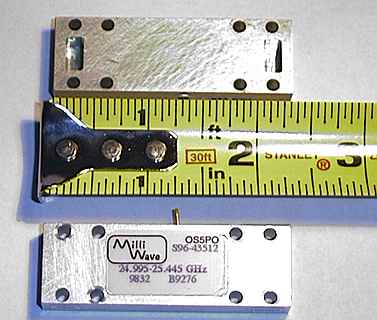
Photo above: Milliwave half watt PA |
In January 2001 I acquired a 500mW solid state PA and immediately installed it in the transverter described above. For how I did it and the results achieve please the photo click opposite. |
| In early 2003 I increased the transmit power out to two watts when I was fortunate enough to acquire a mm Tech solid state PA from a friend in the USA. Details of this modification to my transceiver can be seen by clicking here. |