|
Over the past
few years I have been operating with ssb and cw on the 24GHz band
with the transverter described elsewhere
in these pages. The RF power output was initially very low,
just 200 to 300 microwatts from a "barefoot" DB6NT mixer
but, as time went on, I increased the power to firstly 90 milliwatts,
with a 4 stage DB6NT amplifier (also used in reverse as a receive
preamp) and then to 500 milliwatts with
a a surplus Milliwave amplifier purchased from the USA.
Recently, in 2003, some more half watt (Toshiba) amps became,
available at very low cost (a quarter of the Milliwave amp price!),
from Endwave in California and I purchased one as a "standby".
In addition, in early 2003, I was fortunate enough to hear "down
the grapevine" that a well-known East Coast USA microwaver
(name and callsign withheld for obvious reasons!)had a few TWO
WATT power amplifiers for sale. He had been putting these together
for US amateurs and, with a little bit of friendly persuasion, I
managed to coax him into letting me have three units, for G4BRK,
G4LDR and myself. Very recently, September 2003, he kindly offered
to let me have another 4 amps but the UK uptake on these has been
very disappointing indeed, with only the G4ZXO/G4WYZ group responding!
This is a pity because the only way we are going to fully explore
the potential of 24GHz is to increase power output and dish size
in an effort to counteract the much higher path losses experienced
on that band.
The purpose of
this article is to illustrate how I changed the half watt Milliwave
to the two watt milli-TECH amplifier and to point out some of the
pitfalls along the way!
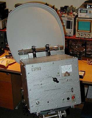 |
The 24GHz transverter
used at G3PHO is shown here on the left. It is manually switched
from transmit to receive by means of a waveguide switch. This
two stage manual switching avoids the need for sequencial
relay changeover. If relays were used, a sequencer would be
essential at this power level to protect both the receive
preamp and the PA itself (this must never see an open or short
circuit). The antenna is a surplus 35cm satellite TV dish
with a small pyramidal horn feed. The equipment is used exclusively
under portable conditions.
Although rather large
by some standards, this gear is nevertheless very rugged and
can withstand rough treatment at times!
The front and top
panels are easily removed for access to the main modules of
the transverter. Apart from the new PA, these modules are
the same as described in the early article found on this website.
|
|
Here on
the right is the mm-TECH two watt PA. The spec sheet
accompanying my unit stated its output was +33.4dBm, measured
at the output ports, for -20dBm in! The power supply is
simple ... just +12VDC at around 1.2 amps maximum.
I was quite
excited at the thought of having this sort of RF available
on 24GHz! Now -20dBm is only 10 microwatts of drive!
Measuring 24GHz RF at such a low level presented a challenge
in itself as my surplus Marconi 6460/3 microwave power meter
isn't as accurate as one would like it to be and tends, like
most older types, to drift at low power settings. The crucial
thing about this amplifier is that more than -15dBm input
could destroy it! I was extremely anxious that this would
not occur as US$325 would thus have gone up in smoke!
Fortunately
I had a 50mW Gunn standard and I used this to calibrate my
power meter at 24GHz and to calibrate the various coaxial
attentuators I would have to use. I found that attentuators
rated to 18GHz were invariably within a fraction of a dB accuracy
on 24GHz also. I am also fortunate in having a calibrated
(20dB)new HP directional coupler for 24GHz, in WG20.
|
 |
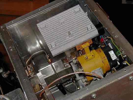 |
The
PA was installed in the transverter as shown left. The half
watt Milliwave amplifier was removed first of course! A large
aluminium heatsink was fitted to the top of the new amplifier,
with the fins upwards so as to maximise the heat dissipation.
The new PA has WG20 (WR42) ports so I was able to easily bolt
it up to the existing waveguide components in the transverter,
i.e the short bend section feeding the waveguide switch and
the WG-SMA transition used on the input port. |
|
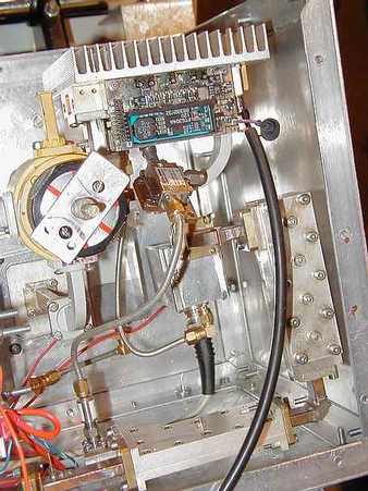
The 10 microwatts
drive was kept to this low figure by using a 3dB attenuator
on the output of the 3dB splitter TX port (lower left in the
photo on the right here). This reduced the 150 microwatts
at this point to 75 microwatts. Further attentuation was achieved
by using some lossy coax and a 24GHz connectorised circulator
used as an isolator on the PA input.. This unusual combination
of items was arrived at by trial and error and the rule "it
it works don't touch it" was then applied!
The lossy
coax bends its way up from the splitter transition at the
foot of this photo to the isolator shown just below the PA,
The thick black cable is the +12VDC feed. On the far right
is a three stage, post mixer, cavity filter, essential with
the IF being 144MHz.
To see these
various modules and the way in which the PA has been incorporated
into the transverter click here
for a block diagram of the complete system.
|
 |
|
RESULTS:
The
RF output measured at the feedhorn end of the 30cm length
of waveguide WG20 (WR42) feeding the dish is 1.8 watts. I
am quite happy with this figure as it represents what is being
radiated after taking into account switching and WG transition
losses in the system as well as any losses involved with the
connectors and transitions in the power measuring setup.
In
the field, the equipment works very well. The PA can be left
in the TX mode with full CW drive for many minutes at a time,
with no noticeable heating of the module. During the summer
of 2003 it was used in air temperatures of up to 37 degrees
Celcius in a "rare" British summer! The PA worked
fine .... the local oscillator stability was another matter!
Reports invariably include the comments, "big signal",
"I can hear you over a wide arc", etc, and reports
sent back are now quite a bit lower in strength than those
received, indicating a power difference of at least 6dB in
favour of my equipment.
PROBLEMS
ALONG THE WAY:
No project
of this nature would be complete without a few headaches!
The first one, after the low power measurement problem, was
that the output power was showing 1 watt with no drive to
the PA ! There was obviously something "taking off"
in the system or there was local oscillator (24.048GHz) leaking
through the filter to drive the PA. Remember that this PA
could produce 2 watts out for only 10 microwatts in!
A check on the spectrum
analyser confirmed that the LO and image filtering was very
good indeed so that was not the cause. I then thought that
the PA might be self-oscillating but drew a blank there as
it did not do so when disconnected from the rest of the transverter.
The problem was solved
when I went around the waveguide switch ports with a small
sheet of "lossy rubber" (removed years ago from
a defunct surplus microwave unit). Pressing this material
around the transmit port and the receive preamp port reduced
the spurious output to almost zero. By then I was convinced
that the problem was actually feedback as I had kept the four
stage, 33dB gain, DB6NT receive preamplifier on during transmit,
the assumption being that the four port waveguide relay would
provide plenty of isolation. The WG switch is in WG22, not
WG20 and, on close examination, it looked like there was a
very small leakage around the flanges at the ports. It was
decided to arrange to switch off the RX preamp during transmit
periods. This cured the problem immediately! The combination
of two very high gain amplifiers bolted onto a common WG switch
was a recipe for trouble!
THE
FUTURE:
The winter
of 2003 will see an improvement in the antenna. I hope to
move up to at least a 60cm offset if not bigger. I have a
friend who uses a 1 metre diameter dish on this band! I have
a suitable tripod for this and also some skill in accurately
setting it up to within a degree azimuth. Perhaps I will arrange
to have 10GHz on the dish also, as an alignment aid.
|
|